Download
1 / 13
140 likes | 385 Vues
Institute for Nuclear Research and Nuclear Energy Dimitrov L.P., Iaydjiev P.S., Mitev G.M. , Vankov I.V. Radiation monitoring at the new GIF++ irradiation facility at CERN. GIF++ is a new Gamma Irradiation Facility being built at CERN.

E N D
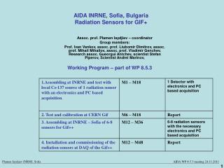
Institute for Nuclear Research and Nuclear Energy DimitrovL.P., Iaydjiev P.S., Mitev G.M., Vankov I.V. Radiation monitoring at the new GIF++ irradiation facility at CERN
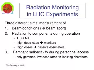
GIF++ is a new Gamma Irradiation Facility being built at CERN. It combines a 16.65 TBeq 137 Cs source with a high-energy particle beam in the SPS H4 beam line. It is expected to be operational in 2015. Our task: to provide a system for online monitoring of the absorbed dose in the devices and objects being irradiated. GIF++
Radiation sensitive p-channel MOS field effect transistors (RadFET). Ionizing radiation causes buildup of positive charge in the gate oxide layer and rises the threshold voltage Vth=a×Db Already tested and used in TOTEM and ATLAS experiments at CERN. LAAS 1600 – sensitive in the range up to few tens of Gy. REM 250 – sensitive in the range up to few tens of kGy. PIN diodes - sensitive to particle fluence. Sensors
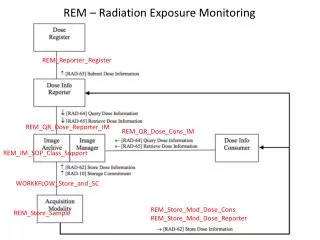
RS 485 CANBUS 36 V DC-DC 3 DETECTOR 1 5 V DETECTOR NODE 1 SPLITTER 1 3 DETECTOR 2 12 DAC 3 DETECTOR 3 3 SPI DETECTOR 4 ADR. 4 PIC 24HJ64 GP504 ADC IN 3 SPLITTER 2 DETECTOR NODE 2 DETECTOR 5 BUS 3 12 DETECTOR 6 3 M U X DETECTOR 7 3 DETECTOR 8 SPARE DETECTOR NODE 12 MAIN CONTROLLER Detector connectivity: 12 boards max. 12-bit ADC Communication: CAN, RS 485 Measurement system block diagram • Power over RS 485, CAN or a dedicated connector DET. NODE MUX 36 V HSCS DAC RADFET1A DET1 I Setting V/I 5 V DECO- DER ON/OFF RADFET1B V/I ON/OFF ADR. Rt0 1 V/I BUS ON/OFF DET2 DET3 DET4 OUT ADR. DETECTOR NODE M U X HSCS – High Side Current Sensor, V/I – 36 V-to-I Converter
Main controller unit (in a 6U crate). 50m cable from each detector node to a passive splitter box. Up to 4 detector boards can be connected to the splitter, using shorter cables. On-site layout
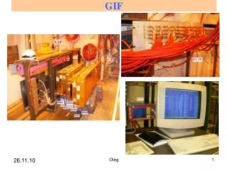
Two boards containing 1 LAAS and 1 REM device were irradiated. The LAAS devices showed about 16% difference in threshold voltage. The REM devices returned almost identical response. The system achieved 8mV input sensitivity (36 V full scale) RESULTS from the test run at GIF
The measurement system has been successfully tested and is ready for integration with the GIF++ control system. The communication protocol with the GIF++ control system has yet to be defined and implemented. The REM devices should be further irradiated at GIF++ to obtain a calibration curve beyond the initial region. conclusions
The “Radiation Sensors for Gif++” task is part of the Advanced European Infrastructures for Detectors at Accelerators (AIDA) project, co-funded by the European Commission under FP7 Research Infrastructures, grant agreement no 262025 and by INRNE (Sofia) - Bulgarian Scientific Fund, Ministry of Education, Youth and Science. Thank you for your attention