Download
1 / 51
530 likes | 875 Vues
Timing and Constraints. “The software is the lens through which the user views the FPGA.” -Bill Carter. Outline. Basic Timing (comb. and sequential) Block timing models LUTs BRAM Multipliers Some standard design timing tricks Constraints Timing

E N D
Timing and Constraints “The software is the lens through which the user views the FPGA.” -Bill Carter
Outline • Basic Timing (comb. and sequential) • Block timing models • LUTs • BRAM • Multipliers • Some standard design timing tricks • Constraints • Timing • Geometric (pinning & arrangement • Combinations • Best tools • Experience • Insight
Propagation Delay LUT Tpd is called “Tilo”
Routing Delays • FPGA datasheets do not give details on routing delay. Hence: • Routing delays not known to designer until design is placed and routed • Delays for early silicon are frequently still under analysis • Software maintains best source for the real timing • FPGA datasheets do provide times associated with incremental silicon blocks
Virtex style logic tile Comment: CLE with IMUX and OMUX is what we Call the “CLB”
What you may find inside the Interconnect block Little black splotches Are muxes or little PIPs to make selectable Attachments….
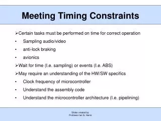
Some standard timing tricks • Load splitting (aka fanout reduction) • Identify sites driving large number of loads • Insert buffered version of the signal with multiple buffers each handling a piece of the total load • Result usually faster • Pipelining • Insert flip flop stages to reduce setup time restrictions • Increases clocking speed, at expense of added latency
Pipeline solution Each flip stage can operate at faster Rate than before, but result goes valid After TWO clocks.
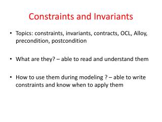
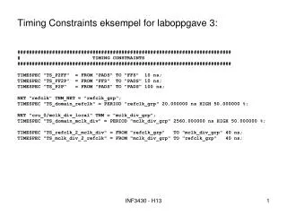
Constraints • More options than we will discuss today • High level, global constraints = big payoff • Will compare a couple of designs across multiple constraints/combinations to illustrate: • 32 bit adder (inherent internal constraint) • Combinational suggests tPD constraints • 32 bit shifter (very malleable) • Sequential suggests Fmax or cycle constraints
Spartan 3S50 TQ144
Big Adder module Big_Adder1( input [31:0] A, input [31:0] B, output [32:0] SUM ); assign SUM = A + B; endmodule
Change constraint • Original unconstrained looks ~same as the nominal 20 nsec constraint. • 20 nsec constraint came in at 11.83 nsec. • Push it down a little, to say 11 nsec and see what happens……
Adder with 11 ns constraint original new
Timing Improvement Wizard Screen 1
TIW Screen 2
TIW Screen 3 Bad news ~78% of the Delay is due to logic Suggests need for faster part
Note Several bits Are out of spec
Interesting… Comment: Recompiled On -5 version (original =-4) Faster design Meets time Without Shift to right?
Comments • Free pinning, free routing gave a result and revealed that 11.83 nsec possible • Free pinning, constrained to 11 nsec revealed 11 nsec is NOT possible (for -4 part) ~78% time spent in silicon delay ~22% time spent in routing delay Faster part (-5) hits 11 nsec, with centered design. Faster part won’t hit 10 nsec when constrained (please experiment for yourself!)
“Big_Shifter” Code module Big_Shifter( input C, input ALOAD, input SI, input [31:0] D, output SO ); reg [31:0] tmp; always @(posedge C or posedge ALOAD) begin if (ALOAD) tmp = D; else begin tmp = {tmp[30:0], SI}; end end assign SO = tmp[31]; endmodule
clock Serial out Clock net Serial in
From “FloorPlan IO Pre-Synthesis” Just defining at the BANK level (versus explicit PADs)
Placing half pins on Bank 0 Shifted the design around But still met timing…..
Closing Comments • The ISE constraints guide is online • It has timing, placement, grouping, relational and synthesis level constraints for both VHDL and Verilog • MOST designers prefer to have a design.ucf file as a separate item. • Best results most often by writing in RTL with .ucf file • Best approach is to experiment using small designs to see what the results are • Examine various reports • Look at “world view” • Pay attention to advice from S/W