Download
1 / 24
240 likes | 339 Vues
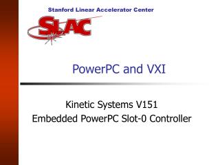
Present Uses of the Fermilab Digital Signal Receiver VXI Module. Brian Chase,Paul Joireman, Philip Varghese RF Embedded Systems (LLRF) Group. Digital Signal Receiver (DSR). 8 Channel Digital Receiver VXI Module 65 MSPS AD6644 ADCs with AD6620 DDC ADSP21062 Floating Point DSP

E N D
Present Uses of the Fermilab Digital Signal ReceiverVXI Module Brian Chase,Paul Joireman, Philip Varghese RF Embedded Systems (LLRF) Group
Digital Signal Receiver (DSR) • 8 Channel Digital Receiver VXI Module • 65 MSPS AD6644 ADCs with AD6620 DDC • ADSP21062 Floating Point DSP • Sync modes in 2 channel pairs • External sample trigger, front panel or back-plane for TBT mode • Differential inputs on DB15 connectors or SMB option • Daughter card for each channel pair with DAC and digital control • 4 12 bit DAC front panel outputs • 130 dB dynamic range at /square root Hz
DSR Operational Status • Main Injector • 53 MHz and 2.5 MHz radial position and beam phase detection for LLRF beam control loops • ECBPMD (Recycler) - Development System • H=1 (89 kHz) BPM processing on four detectors for over one year. • ECBPM (Wideband) - Operational System • 32 kHz and pulse mode processing on 19 BPMs
Beam/Gain Changes Pbar/high Elec/high Elec/low Pbar/high
Pulsed Mode v. Pbar Pulsed mode Pbar
Noise Measurements 100 Hz Bandwidth position data
Noise Measurements 5 Hz Bandwidth position data
ECBPM Software Metrics • Language C/C++ • Operating System VxWorks 5.4 • Development Effort 3-4 “man-months” • Lines of Code 10,000 (50 % COM) • Functions • Manage DSR resources in VXI mainframe • Provide Acnet/MOOC interface for reading/setting and basic control of BPM system. • Provide high-level functionality to user to configure system for different operational modes
DSR Shared Library Metrics • Language C • Operating System VxWorks 5.4 • Development Effort 2-3 “man-months” • Lines of Code 6700 (60 % COM) • Functions • “Glue layer” to support communication between application software and DSR hardware. • Encapsulate DSR hardware using “object-based” methodology. • Data: DSP hardware addresses • Methods • Creation/initialization • Informational - DsrDump, DsrParamInfo • Client Vector Interrupts – requests for DSP services
DSP Software Metrics • Language C and Assembly • Operating System N/A • Development Effort 3-4 “man-months” • Lines of Code 4700 (50 % COM) • Functions • Configure hardware in a default initial state • Communication with DSR hardware external to DSP, DDC (AD6620) chip, VXI reset line, and hardware test points. • Low-level data processing and analysis including acquisition, filtering and engineering calculations.
TESTDSR Software Metrics • Language C/C++ (LabView) • Operating System VxWorks 5.4 • Development Effort 2 “man-months” • Lines of Code 3000 (60 % COM) • Functions • Test low-level hardware functionality of DSR board • Five test modes • Memory test, ADC test, Frequency sweep, Trim Potentiometers, Power Sweep • Labview interface to control testing procedure
DSR, Tev Module Comparison • Tev Module: • 5 MHz BW • Analog position processing • Intensity triggered position sample once per turn. • No turn marker used. • DSR: • <<1 MHz BW • Digital position processing • Intensity triggered once per turn or pure narrow band • Turn marker is optional
Process Bandwidth Considerations • Wideband > 2 MHz • Good SNR • Systematic errors are hard to manage. • Signal looks good but may have average error • Narrow Band • Good SNR with large fill factor • Even with poor SNR, average is correct.