Download
1 / 25
290 likes | 788 Vues
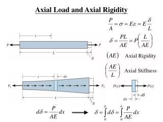
9. Axial Capacity of Pile Groups. CIV4249: Foundation Engineering Monash University. P shaft. Axial Capacity. F u. F u + W = P base + P shaft. W. Shear failure at pile shaft. P base. Bearing failure at the pile base. P shaft,t . Tension Capacity. T u - W = P shaft,t < P shaft,c.

E N D
9. Axial Capacityof Pile Groups CIV4249: Foundation Engineering Monash University
Pshaft Axial Capacity Fu Fu + W = Pbase + Pshaft W Shear failure at pile shaft Pbase Bearing failure at the pile base
Pshaft,t Tension Capacity Tu - W = Pshaft,t < Pshaft,c Shear failure at pile shaft
Very Large Concentrated Weight Large Distributed Weight Low Weight Applications Soft to Firm Clay Dense Sand Strong Rock
Pug Group Capacity Pile Cap • Overlapping stress fields • Progressive densification • Progressive loosening • Case-by-case basis Pug¹n.Pup Pug = e.n.Pup
Clay Sand d s Rock Efficiency, e Pile Cap n = 5 x 5 = 25 Soil Type Number of Piles, n Spacing/Diameter s/d typically > 2 to 3
Free-standing Groups Capped Groups Flexible Cap Rigid Cap Types of Groups
13/16 11/16 8/16 û Feld Rule for free-standing piles in clay A B B B A reduce capacity of each pile by 1/16 for each adjoing pile B C C C B e = 1/15 * (4* 13/16 + 8 * 11/16 + 3 * 8/16) = 0.683 A B B B A
n = # cols = 5 e = 1 - q (n-1)m + (m-1)n 90 mn q = tan-1(d/s) m = # rows = 3 d=0.3 s = 0.75 Converse-Labarre Formula for free-standing piles in clay e = 0.645
Flexible Cap D L,B Block Failure PBL = BLcbNc + 2(B+L)Dcs cs Nc incl shape & depth factors cb Pug = min (nPup,PBL)
1 = 1 + n2P2up e2 P2BL Empirical Modification PBL = BLcbNc + 2(B+L)Dcs Pug = min (nPup,PBL) 1 1 1 P2ug = n2P2up + P2BL nPup n
Block Failure Flexible Cap D = 20m cs = cb = 50 kPa d = 0.3m L = B = 5m
Capped Groups Bc x Lc Rigid Cap Ptotal = Pgroup + Pcap for single pile failure, Pcap = ccapNc [BcLc - nAp] for group block failure, Pcap = ccapNc [BcLc - BL] B x L
Efficiency increases 1.0 72 capped 0.9 0.8 0.7 72 free-standing 0.6 0.5 0.4 • s/d 0.3 1 2 3 4
Piles in Granular Soils • End bearing - little interaction, e = 1 • Shaft - driven • For loose to medium sands, e > 1 • Vesic driven : 1.3 to 2 for s/d = 3 to 2 • Dense/V dense - loosening? • Shaft - bored • Generally minor component, e = 1
Elastic Analysis Methods • based on Mindlin’s equations for shear loading within an elastic halfspace • Poulos and Davis (1980) • assumes elasticity - i.e. immediate and reversible • OK for settlement at working loads if reasonable FOS • use small strain modulus
Ap Ep Es As Definitions Pile Stiffness Factor, K Area Ratio, Ap K = RA.Ep/Es RA = Ap / As
% load at the base Pile top settlement d Floating Pile Ep b = boCKCn Es,n L h r = P.IoRKRLRn / Esd Solutions are independent of soil strength and pile capacity. Why? Rigid Stratum
0.5 Floating pile example P = 1800 kN b = boCKCn r = P.IoRKRLRn / Esd Ep = 35,000 MPa Io = 0.043 RK = 1.4 RL = 0.78 Rn = 0.93 r = 4.5mm bo = 0.038 CK = 0.74 Cn = 0.79 b = .022 Pb = 40 kN 25 32 Effect of : L = 15m db/d = 2 h = 100m n = 0.3 Es = 35 MPa Rigid Stratum
d Pile on a stiffer stratum • % load at the base Ep b = boCKCbCn Es,n L • Pile top settlement r = P.IoRKRbRn / Esd Stiffer Stratum Eb > Es
d Layered Soils Ep E1,n1 L E2,n2 Es = 1 SEi hi L Stiffer Stratum Eb > Es
0.5 Stiffer base layer example P = 1800 kN b = boCKCbCn r = P.IoRKRbRn / Esd Ep = 35,000 MPa n = 0.3 Io = 0.043 RK = 1.4 Rb = 0.99 Rn = 0.93 r = 4.5 mm bo = 0.038 CK = 0.74 Cn = 0.79 Cb = 2.1 b = .0467 Pb = 84 kN 25 Es = 35 MPa Eb = 70 MPa Effect of: Es = 15 MPa to 15m
Movement Ratios • MR is ratio of settlement to PL/AE • Focht (1967) - suggested in general : 0.5 < MR < 2 • See Poulos and Davis Figs 5.23 and 5.24
Floating Piles End bearing piles Pile group settlment Single pile settlement is computed for average working load per pile