Download
1 / 24
270 likes | 457 Vues
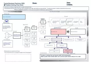
Study on 10kV XLPE Cable with Defects Based on Oscillating Wave Test System. Lu Guojun. Guangzhou Power Supply Bureau of China South Grid. 1.Introduction. 2.OWTS Testing System. 3.Process of the Experiment. 4. Results. 5. C onclusions. 1.Introduction.

E N D
Study on 10kV XLPE Cable with Defects Based on Oscillating Wave Test System Lu Guojun Guangzhou Power Supply Bureau of China South Grid
1.Introduction 2.OWTS Testing System 3.Process of the Experiment 4. Results 5. Conclusions
1.Introduction The advantages of the cable transmission: Save area, beautify the urban environment 10kV XLPE Cable in Guangzhou: Until now, the number have reached to86,282 km, and maintain a high growth rate last three years. PD measuring systems: Testing the quality of cable installation & Finding defects in the operation. OWTS was judged to be the best system for the considered cases of application.
1.Introduction Based on the laboratory test carried out on 351m 10kV XLPE power cable in which there are some typical PD defects, the method of OWTS for detecting PD in XLPE cable and its accessories was introduced.
1. Introduction 2.OWTS Testing System 3.Process of the Experiment 4. Results 5. Conclusions
2.OWTS Testing System OWTS testing system schematic diagram
2.OWTS Testing System Partial discharge located by pulse reflection
1. Introduction 2.OWTS Testing System 3.Process of the Experiment 4. Results 5. Conclusions
3.Process of the Experiment Experimental equipment and its connection
3.Process of the Experiment step1 step2 step3 step4 step5 L2: cable terminals outer semi-conducting layer too long L3: cable terminal main insulation layer non-smoothing L1: cable terminals outer semi-conducting layer non-smoothing
3.Process of the Experiment step1 step2 step3 step4 step5 L1: impurities in cable terminal L3: scratches in cable terminal main insulation layer
3.Process of the Experiment step1 step2 step3 step4 step5 L2: flash in pressing joint pipe & cable terminal’s outer semi-conducting layer too long L3: salty water in joint & scratches in cable terminal main insulation layer L1: winding cable joints pressing joint pipe with insulating tape & impurities in cable terminal
3.Process of the Experiment step1 step2 step3 step4 step5 L2: flash in pressing joint pipe L3: salty water in joint L1: winding cable joints pressing joint pipe with insulating tape
3.Process of the Experiment step1 step2 step3 step4 step5 L3: salty water in joint& squeezing cable L2: flash in pressing joint pipe& saw traces in outer insulation
1. Introduction 2.OWTS Testing System 3.Process of the Experiment 4. Results 5. Conclusions
4. Results The following figures PD of Cable terminals outer semi-conducting layer non-smoothing. The left pictures show the relationships between partial discharge and the voltage, right ones illustrate the PD and location of the PD.
4. Results RELATIONSHIPS BETWEEN CHARACTERS OF PD AND DEFECTS IN CABLE(1)
4. Results RELATIONSHIPS BETWEEN CHARACTERS OF PD AND DEFECTS IN CABLE(2)
4. Results RELATIONSHIPS BETWEEN CHARACTERSS OF PD AND DEFECTS IN CABLE(2)
4. Results RELATIONSHIPS BETWEEN CHARACTERSS OF PD AND DEFECTS IN CABLE(2)
4. Results RELATIONSHIPS BETWEEN CHARACTERSS OF PD AND DEFECTS IN CABLE(2)
1. Introduction 2.OWTS Testing System 3.Process of the Experiment 4. Results 5. Conclusions
Conclusion 1 According the figures and tables in the experiment, the corresponding relationships between PD and the kinds of defects can be built initially. OWTS is effective in detecting defects in terminals and joints. Some defects in cable itself were hard to be detected by the OWTS even under 2U0. Conclusion 2 The noise level was low because the experiment was carried out in the high voltage laboratory. Extracting the PD signal from the noise would seem difficult in a field situation. Conclusion 3 The traveling wave location is the key in the OWTS test, which detects incident wave and reflective wave. The cable used in experiment was short distance and contains only one joint. The validity of location of the OWTS is still worthy to prove