Download
1 / 14
340 likes | 837 Vues
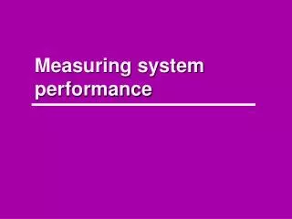
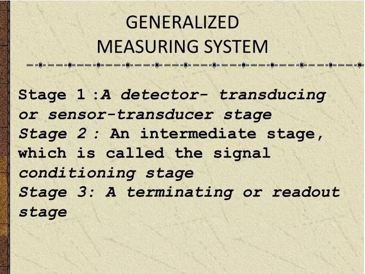
GENERALIZED MEASURING SYSTEM. Stage 1 : A detector- transducing or sensor-transducer stage Stage 2 : An intermediate stage, which is called the signal conditioning stage Stage 3: A terminating or readout stage. INUPUT IDENTIFICATION.

E N D
GENERALIZEDMEASURING SYSTEM Stage 1 :A detector- transducing or sensor-transducer stage Stage 2 : An intermediate stage, which is called the signal conditioning stage Stage 3: A terminating or readout stage
INUPUT IDENTIFICATION • Measured are classified according to their time relationship . • According to the rate of variation of the measured with respect to time: is classified into static and dynamic. • According to the fashion of variation with time: is classified as analog and digital.
Static or Dynamic Static: The measured does not change or not rapidly change with time. Of course, the non-changed measured is the most easily measured quantity. The meter pointer has no difficulty in eventually reaching a definite indication INUPUT IDENTIFICATION
Dynamic • Steady-state &Transient • The measured rapidly changed with respect to time. This case represents a real measurement challenge. • There are two general form of dynamic input: • steady-state periodic and transient. • The steady-state periodic quantity is one whose magnitude has a definite repeating time cycle. • The time variation of a transient magnitude does not repeated. • This condition represents the most severe measuring state. Static or Dynamica)Static quantity
Analog or Digital Analog quantity The measured varies with time in a continuous manner. For instance, the speed of an automobile, as it starts from rest, and the voltage in utility power lines. Temperature, fluid flow, pressure, stress, and strain are normally behave in analog manner.
Digital quantity Analog or Digitalc) Analog quantitry Digital quantity is that quantity varies in a stepwise manner between two distinct magnitudes: a high and a low voltage, for instance. Digital quantities are preferred in measuring systems. Noise problem is reduced or eliminated, data transmission is simpler, and computers are designed to process digital information. Therefore it may be preferred in some cases to convert analog type input to an equivalent digital signal
FIRST STAGE SENSING-TRANSDUCING STAGE • The primary function of this stage is to detect or sense the measured. • A transducer is a device that transforms one physical effect to another. In most cases , the physical variable is transferred into an electric signal Transducer classified as:- -Mechanical : Bourdon tube -Hydraulic-pneumatic : Float, propeller -Optical :Photographic film, photoelectric cell - Electrical :Resistance, coil, condenser. d)Digital quantity
SECOND or INTERMEDIATE STAGE SIGNAL-CONDITIONING STAGE The purpose of the second stage is to modify the transduced signal so that it will be suitable for the third stage. • increase the amplitude of the signal to the level required to drive the final terminating stage. • Filtration process is carried out at this stage, whereas The desired signal is extracted from the extraneous input. • Modification of the signal to be suitable for remote controlling is also carried out in this stage. • In addition basic operation such as, integration, differentiation, summation could be performed in this stage. FIRST STAGE SENSING-TRANSDUCING STAGE
THIRD OR TERMINATING or FINAL STAGE The final stage expresses the measured in comprehensible to one of the human sense or to a controller. The output device may be Indicators Displacement type: moving pointer and scale, moving scale and index, light beam and scale, electron beam and scale (CRO), liquid column Digital type : Direct alphanumeric readout -Recorders: Digital printing, inked pin and chart, light beam and photographic film, magnetic recording. Processors: Various type of computing systems or controlling systems SECOND or INTERMEDIATE STAGE SIGNAL-CONDITIONING STAGE
Gage for Measuring Pressure in Automobile Tires The piston-cylinder combination constitutes a force-summing apparatus sensing and transducing pressure to force. As a secondary transducer, the spring converts the force to displacement. Finally, the transduced input is transferred without signal conditioning to the scale and index for read out THIRD OR TERMINATING or FINAL STAGE
As shown in Fig. below, The accelerometer provides an analogous voltage to the acceleration. • A filter is used to eliminate the unwanted high frequency components. • The signal is then integrated w.r.t. time, thereby providing a velocity-time relation. • The signal is then amplified to the level necessary to drive the read out stage. • Finally, the output may be in the form of a trace on a photographic paper. Fig. 2.3 Gage for measuring pressure in automobile tires
Measuring System for Measuring the Velocity of a Vibrating Body