Download
1 / 20
210 likes | 318 Vues
First Lasing of the ALICE Free Electron Laser. David Dunning On behalf of the ALICE FEL team (Jim Clarke, Neil Thompson, Mark Surman and Andy Smith), and all the ALICE team.

E N D
First Lasing of the ALICE Free Electron Laser David Dunning On behalf of the ALICE FEL team (Jim Clarke, Neil Thompson, Mark Surman and Andy Smith), and all the ALICE team
On October 23rd 2010, the ALICE infra-red free electron laser (FEL) at Daresbury Laboratory was successfully operated for the first time. This is the first FEL of its type to operate in the UK, and the first FEL operating with an energy recovery linac accelerator in Europe. Introduction • What it is • Motivation • How it was done • Results so far • Future prospects
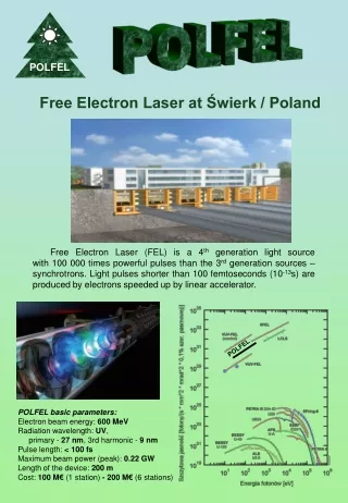
Motivation for the ALICE FEL • Why free electron lasers? • Light sources have served as a powerful tool for scientific experiments for decades. • A free electron laser is an accelerator-basedlight source with an exceptionalcombination of properties : • Applicable over a very wide wavelength range (THz to x-ray demonstrated so far) • Easily tuneable • High repetition rate • Short pulse • High brightness/peak power • … • FEL facilities increasingly significant: • FLASH, LCLS • Enabling new science Why this particular free electron laser? • A step towards developing a cutting-edge FEL facility for the UK. • The UK doesn’t have an FEL facility, but has aspirations to develop one: • The ALICE FEL has allowed the team proposingadvanced FELs for these facilities to develop the skills to design, build and operate such a machine. • The ALICE FEL is an infra-red oscillator FEL - it’s not the first of its kind, but it puts us in a position to seriously consider advanced concepts in a future machine. • In addition, a free electron laser is kind of the ultimate test for our prototype accelerator facility.
How an Oscillator FEL works • A hole in one cavity mirror outcouples a small fraction of the stored radiation • An optical cavity stores the emitted radiation. The cavity length is set such that the cavity roundtrip time matches the repetition time of the electron bunches UPSTREAM MIRROR DOWNSTREAM MIRROR UNDULATOR ELECTRONS ELECTRONS • The undulator is a periodic magnetic field which causes the electrons to oscillate transversely and emit synchrotron radiation. The transverse component of the electron velocity allows the exchange of energy between the electrons and the stored radiation field • The interaction causes the electrons to bunch at the radiation wavelength, and so emit coherently • Electron bunches arrive with a fixed repetition rate Key components: electron beam, undulator and optical cavity
ALICE FEL layout UPSTREAM MIRROR DOWNSTREAM MIRROR UNDULATOR ELECTRON PATH Key components: electron beam, undulator, optical cavity + diagnostics…
Electron Beam DOWNSTREAM MIRROR UNDULATOR UPSTREAM MIRROR BUNCH COMPRESSOR ELECTRON PATH
Optical Cavity UPSTREAMMIRROR DOWNSTREAM MIRROR
Diagnostics for IR radiation LASER POWER METER DOWNSTREAM ALIGNMENT HeNe FEL BEAMLINE TO DIAGNOSTICS ROOM PYRO-DETECTORon Exit Port 2 SPACE FOR DIRECT MCT DETECTOR SPECTROMETER Based upon a Czerny Turner monochromator MCT (Mercury Cadmium Telluride) DETECTOR on Exit Port 1
FEL Commissioning Strategy • In order for the FEL to operate we needed to co-align: • Undulator axis • Optical cavity axis • Electron beam axis
FEL Commissioning Strategy 3. Downstream Mirror aligned using Upstream alignment laser (HeNe) 6. Cavity length scanned looking for enhancement of spontaneous emission, then LASING. 5. Electron Beam steered to Alignment Wedges 4. Upstream Mirror aligned using Downstream alignment laser (HeNe) 2. Alignment Wedges and Downstream Mirror aligned optically using Theodolite 1. Undulator Arrays and two Optical Targets surveyed onto Reference Axis with Laser Tracker SPECTROMETER ALIGNMENT WEDGES ALIGNMENT MIRROR ALIGNMENT MIRROR MCT DETECTOR UNDULATOR ARRAYS OPTICAL TARGET OPTICAL TARGET DOWNSTREAM FEL MIRROR DOWNSTREAM FEL MIRROR POWERMETER REFERENCE AXIS OPTICAL TARGET OPTICAL TARGET ELECTRONS CCD VIEWER CAMERAS CCD VIEWER CAMERAS CCD VIEWER CAMERAS CCD VIEWER CAMERAS CCD VIEWER CAMERAS LASER TRACKER HeNe HeNe UPSTREAM MIRROR DOWNSTREAM MIRROR UNDULATOR
ALICE IR-FEL Commissioning • 2009 • November: FEL Undulator installation begins. • 2010 • January: FEL Undulator and Cavity Mirrors installed and aligned: all hardware in place to start commissioning. • Throughout 2010: FEL programme proceeded in parallel with installation & commissioning of EMMA, plus THz programme. One shift per day for commissioning. Of available beam-time, FEL programme got 12%. • February: First observations of undulator spontaneous emission. • Stored in cavity immediately, indicating transverse pre-alignment reasonable. • Scanned cavity length but no enhancement (limited to 40pC bunch charge, design was for 80pC). • May/June: Spectrometer installed and tested. First spectra of undulator spontaneous emission. • Analysis of spontaneous emission used to optimise electron beam steering and focussing • Also indicated pre-alignment was acceptable. 17th November 2009 4th February 2010 13th June 2010
ALICE IR-FEL Commissioning 28th June 2010 • 2010 (continued) • June: Strong coherent emission with dependence on cavity length • Indication of correct cavity length. • BUT NO LASING! Gain not exceeding losses. • Identified need to: • Reduce losses • Increase gain • Get reliable measure of cavity length • July: Changed outcoupling mirror from 1.5mm radius to 0.75mm to reduce losses • Re-gained cavity enhancement but still no lasing • Installed encoder to get cavity length measurement • Mirror radius of curvature tested, and matched spec. • EO measurements indicated correct bunch compression. • 17th October: installed a Burst Generator to reduce laser repetition rate by a factor of 5, from 81.25MHz to 16.25MHz. This enabled us to increase the bunch charge to >60pC and hence increase the gain… 27th July 2010 17th October 2010
23rd October 2010: ALICE FEL First Lasing First Lasing Data: 23/10/10 Simulation (FELO code)
Results • Highest recorded average power = 32 mW • Macropulse length = 100 μs, repetition rate = 0.1 s. • Micropulse repetition rate = 16 MHz, micropulse spacing = 0.0615 μs, i.e. 1626 pulses per macropulse, 16260 pulses per second. • Energy per pulse = 32mW/16260 = 2 μJ per pulse. • Average power within a macropulse = 32 W • Transmission efficiency of vacuum window=0.7 – so power from FEL ~1.4x higher. • The FEL pulse duration has been inferred from the spectral width to be ~1 ps The peak power is therefore ~3 MW.
Further Progress • The first demonstration of wavelength tuning of the ALICE FEL has been carried out. By increasing the undulator gap the wavelength was continuously tuned from 8.0 μm to 5.7 μm, with lasing maintained throughout the range. FEL Spectra at Different Gaps
Further Progress • The FEL radiation has been transported to a diagnostics room, and the first measurements of the transverse profile have been made.
ALICE FEL Future Plans Simulation results • Improved electron beam set-ups with reduced energy spread and jitter. • Improve transport of FEL beam to diagnostics room, then full output characterisation. • Reduced Mirror ROC to improve gain, plus selection of outcoupling hole sizes to optimise output power. • Plan to run and characterise at two different energies • 27.5MeV (5-8µm) • 22.5MeV (7-12µm)
Summary • Further work on characterising the FEL performance and output is continuing, with lasing now achieved routinely. The successful operation of the free electron laser is a significant achievement for the team, and provides invaluable experience for future FEL facility proposals. • Thanks to everyone who contributed to the project, and thanks to you all for listening!
ALICE FEL Layout ALICE FEL Systems Schematic SPECTROMETER MCT DETECTOR ALIGNMENT WEDGES ALIGNMENT MIRROR ALIGNMENT MIRROR (OPTICAL TARGET) INFRA-RED POWER METER ELECTRONS ELECTRONS CCD VIEWER CAMERAS (OPTICAL TARGET) HeNe HeNe UPSTREAM MIRROR DOWNSTREAM MIRROR UNDULATOR