Download
1 / 19
190 likes | 351 Vues
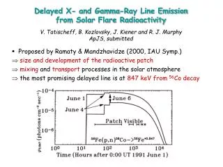
Diagnostics of Flare Plasma Using Pulsations in Microwave and X-Ray Emission. A.V.Stepanov 1 , Yu.G. Kopylova 1 , K.Shibasaki 2 , Yu.T.Tsap 3 , V.F.Melnikov 4 , and T.B.Goldvarg 5 1 Pulkovo Observatory, St.Petersburg, Russia 2 National Astronomical Observatory, Nobeyama, Japan

E N D
Diagnostics of Flare Plasma Using Pulsations in Microwave and X-Ray Emission A.V.Stepanov1, Yu.G. Kopylova1, K.Shibasaki2, Yu.T.Tsap3,V.F.Melnikov4, and T.B.Goldvarg5 1Pulkovo Observatory, St.Petersburg, Russia 2National Astronomical Observatory, Nobeyama, Japan 3Crimean Astrophysical Observatory, Nauchny, Crimea, Ukraine 4Research Institute of Radiophysics, Nizhny Novgorod, Russia 5Kalmyk State University, Elista, Russia Solar Physics with the Nobeyama Radioheliograph (Nobeyama Symposium 2004) 2004 October 26 – 29 Kiyosato , Japan
TRACE and VLBA/VLA → magnetic loops are fundamental structures of coronaeof the Sun and late type stars (Bray et al. 1991; Benz et al.1998; Schrjiver et al. 1999). Moreover, the loops are typical magnetic elements of accretion discs and young stellar objects. UV Ceti B (Feb 4,1996)VLBA/VLA at 3.6 cm.White circle ~ 0.8 milliarcsec
Parameters of coronal magnetic loops Parameter the Sun red dwarf ---------------------------------------------------------------- Loop length, l cm(1-10)109 2109 - 31011 Loop radius, r cm~108 108 – 109 Plasma density, n cm-31010 - 1011 1010 - 1012 Plasma temperature, T K106 - 107 3106 – 108 Magnetic field, B G102 - 103 3102 – 104 Magnetic mirror ratio, 2 – 100 Alfven velocity, VA cm/s108≥ 108 Emission measure, EM cm-31047 - 1050 1050 - 1053
MHD-oscillations of coronal loops Eigen-modes of plasma cylinder (Zaitsev & Stepanov 1975; Roberts 1983) . Fast magneto sonic (radial) mode, m = 0:
(i) Radial oscillations Fast magneto-sonic waves can undergo strong damping caused by radiation of FMS mode to the environment plasma .The damping rate is (Meerson, Sasorov, Stepanov 1978) (3) There is no damping for e/i < k||2/ k┴2. r2/l2, e.g. for comparatively thick loop. In this case we have an ideal resonator for FMS-waves. Moreover, the plasma density inside flare loops can be from two to three orders higher than outside (Doschek 1994). So, there is a jump of impedance for FMS waves. Acoustic damping of the radial FMA oscillations of coronal loops caused by emission of waves into the surrounding medium becomes insignificant (Zaitsev and Stepanov 1982; Kopylova et al. 2002). Therefore, the analysis will be restricted to the dissipative processes only. Under solar flare condition the most important damping mechanisms for fast sausage mode are thermal conductivity and ion viscosity (Stepanov, Kopylova, Tsap et al. 2004): Here θis the angle between the magnetic field and wave vector . Comparing the damping rates: for the plasma beta β≈ 0.1 we find that ion viscosity less important as compared to the electron thermal conductivity if θ < 78o.
MHD-approach: radial and ballooning modes(ii) Oscillation regime of ballooning mode Curvature of magnetic field is important for ballooning mode. Small deviations of plasma tongue having the scale L1= l/N where , l ≈ πR, R is the curvature radius of a loop, N is the number of plasma tongues in a loop. Oscillations occur as the result of acting of two forces: the force dealing with gas pressure gradient and magnetic field line curvature F1 ~ p/R, and the back-ward force due to the magnetic field tension F2 ~ B2/R . Dispersion equation for ballooning mode with taking into account the scale of disturbances can be represented as (Mikhailovskii, 1974) where is typical scale of plasma density inhomogeneity across the magnetic field, is the transverse scale of plasma tongue. Period of the ballooning oscillations → Ideal MHD provide evidence for the analogy between the flute (ballooning) and FMA modes (Burdo et al. 2000; Stepanov et al. 2004). So, to determine the damping rate of ballooning mode we can use FMS expressions.
MHD-approach: radial and ballooning modes(i) Diagnostics of coronal loop plasma Nobeyama flare observations (≥17 GHz) → optically thin, τ < 1 Flux F = ηΩd ~ B0.90δ-1.22Modulation depth M = (Fmax – Fmin)/ Fmax M = 2ξΔB/B, ξ = 0.90δ- 1.22 (a) Origin of loop MHD oscillations: flare energy release, chromosphere evaporation, … Thus plasma beta β ≈ 2ΔB/B = M/ξ(b) For θ < 78o electron thermal conductivity play the main contribution to the damping of both FMS and ballooning modes. Quality (c) Oscillation period PFMS = r (cs2 + VA2) -1/2Pball= 2l/VAN (d) From Eqs. (a) – (d) → Formulas for calculations of loop plasma parameters using characteristics of radio pulsations caused by ballooning and FMS oscillations
Modulation of gyrosynchrotron emission Consider the effect of radial coronal-loop oscillations B = B0 + ΔB sin ωt on the microwave radiation from solar flares for which the nonthermal gyrosynchrotron mechanism is generally accepted (Bastian 1998). The spectral fluxes for optically thin and optically thick sources: F1 = η1Ωd ~ B0.90δ-1.22, τ1 <1;F2 = η2 Ω/ k2~ B – 1.02 – 0.08δ, τ2 >1 (1) where Ω is the solid angle of the source and d isits characteristic thickness. The emission(η) and absorption (k) coefficientsare expressed by Dulk (1985). In Eqs. (1) the law of magnetic flux conservation (d ~ B -1/2, Ω ~ B -1/2) and moderate diffusion regime of energetic electrons (Stepanov & Tsap, 2002) were took into account. From Eqs.(1) one can see that radio oscillations in optically thin and optically thick sourcesshould be in anti-phase. Modulation depth: M = (Fmax – Fmin)/ Fmax for optically thin and thick sourcesare M1= 2(0.90δ – 1.22)ΔB/B, M2= 2(0.08δ + 1.02)ΔB/B. For the same population of electrons we determined the power-law spectral index:
Modulation of gyrosynchrotron emission: Event of May 23,1990(Qin et al. 1996 Solar Phys.163, 383) Flux Fmax~ 103 sfu, Pulsation period ≈ 1.5 s, Anti-phase at 9.375 and 15.0 GHzModulation depth: M1(15 GHz, τ ≈ 0.1) = 5%, M2(9.4 GHz, τ ≈ 2) = 2.5%.Electron power-law index:≈ 4.4Magnetic field B(δ,θ,τ,νpeak)≈ 190 G (Qin et al: 130 G), νpeak ≈ 10.6 GHz
MHD-approach: radial and ballooning modes(ii) Diagnostics of coronal loop plasma Ballooning oscillationsRadial (FMS) oscillations ________________________________________________________________ χ= 10ε/3 + 2, ε = M/ξ Temperature T is in K, the density n is in cm-3, and the magnetic field B isin G
Modulation of gyrosynchrotron emission: Event of May 8,1998 M3.1 X-class flare NOAA 8210 S15W82 Pulsation period P≈ 16 s Q-factor ≈ 25, Modulation M ≈ 0.3 Ballooning mode oscillations: Number of plasma tongues N = 4 Loop length ≈ 8109 cm The angle θ≈ 66o < 78o (!) → Thermal conductivity is most important for damping of ballooning oscillations. For δ = 4.5 (Lee et al. 2002) one can obtain the loop plasma parameters: Plasma temperature T≈ 4107 K Electron number density n≈ 3.71010cm-3 Magnetic field B≈ 220 G Plasma beta β ≈ 0.11 Nobeyama 17 GHz Yohkoh
Modulation of gyrosynchrotron emission: Event of August 28,1999 Model: Two-loop configuration Ballooning oscillations: P≈ 14 s (compact loop), a gap (00:55:45-56:30 UT) : ballooning instability and hot plasma injection into extended loop Radial FMS oscillation: P≈ 2.4 s (extended loop), started after plasma injection (00:56 UT) Parameter Extended loop Compact loop T ,K 2.5 × 1075.2 × 107 n, cm−3 1.5 × 10¹⁰ 4× 10¹⁰ B, G150280 β 0.04 0.11 __________________________________________________________________ Fit well to soft X-ray diagnostics