Download
1 / 26
260 likes | 394 Vues
TUTORIAL 4 FEATURE MESHING - CREATING HOLES & BEADS. Table of Contents. Section Page Step1. Open MSC.Sofy Database. 3 Step2. Create a Parametric Hole . 4 Step3. Punch a Parametric Hole with Washer. 9 Step4. Create a Parametric Bead. 11

E N D
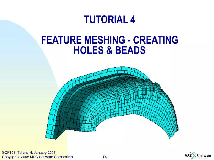
TUTORIAL 4 FEATURE MESHING - CREATING HOLES & BEADS
Table of Contents Section Page Step1. Open MSC.Sofy Database. 3 Step2. Create a Parametric Hole . 4 Step3. Punch a Parametric Hole with Washer. 9 Step4. Create a Parametric Bead. 11 Step5. Create a Cutout hole. 15 Step6. Create Part “reinf”. 17 Step7. Use the Translate command 18 Step8. Create Reinforcement. 19 Step9. Create Rigid RBE2 Element 20 Step10. Create a Flange 22 These parametric features can be used to optimize a design by integrating MSC.SOFY with NASTRAN, DYNA and Optimizers like iSIGHT As in the other tutorials, all menu items that need to be selected will be preceded by a maroon right arrow: >User action. Mouse buttons are indicated as follows: -- 1B = First (left) button -- used for selecting items-- 2B = Second (middle) button -- used for "OK"-- 3B = Third (right) button -- used for View Manipulation & pop-up menusNormally 1B is used, unless otherwise
Step1.Open MSC.Sofy Database. d • Launch MSC.SOFY according to your local configuration. • From the General Toolbar, click on the icon to Open SOFY database or Top Bar (select)>File Menu >Open SOFY DB - to open an existing SOFY database.) • In the file dialog box – goto the directory sofy_inst/SOFY3.0/SOFY_MASTER2/DEMOS/Tutorials_Basic/tutor03_ModelEdit.sof (Exact path may depend on your local installation.) • The following should appear . • Turn off the part "Reference Lines." (Collection block >uncheck box next to part name.) • View Block >Click>RDRW (Redraw) e f
Step2.Create Parametric Hole. Get the proper view to create a hole First, we'll change the part color: • Click with (3B) >WHINR (in Collection Block) • Use 1B >Change Color. • From the pop-up color palette >Cyan color. a c b
Step2.Create Parametric Hole. (Cont’d) d d. View Block >Hole e. On the Top Bar (select) >Mesh Menu >Create Hole f. Go to Pick Menu >Select >Pt. on Element . f e
Step2.Create Parametric Hole. (Cont’d) g MSC.SOFY can pick the exact centroid of the elements – g. Pick menu > click >D. h. This opens the Extended Pick Dialog (EPD). i. On right side of EPD: Pt. On Element Type (select)>@ Centroid. (Do not exit this window - because the default mode - @ Cursor will get activated.) j. Now pick an element in the canvas as shown in the following picture. h j i
Step2.Create Parametric Hole. (Cont’d) k l k. A pop-up window as shown below will appear where you can enter the following parameters1. Diameter of the hole (say 12) 2. Number of rings around the hole (say 2) 3. Number of elements in the inner ring (say 8) 4. Number of levels (transition rings, say 2) to make the transition elements from the ring of elements to the base model. l. Press >Ok to create hole Let's un-do and try with diferent parameters • From Toolbar, General menu (select)>Undo icon to reject the hole creation. • The "Create Hole" command should still be active. (If not, from the Mesh menu (select) >Create hole) • Pick a different location to create a hole with different set of parameters as shown below • Click on >Ok to create hole with new parameters • The new hole created is as shown below . m q
Step2.Create Parametric Hole. (Cont’d) r. Repeat steps m through p again by changing parameters as below s. The new hole created is as shown below . As you try with different parameters, please note the change in the mesh around the hole. r s
Step3.Punch a Parametric Hole with Washer. Use "Create Hole with Washer" command to create a hole through multiple parts. • Punch a hole through the wheelhouse and the new reinforcement: • From >Mesh menu (Top block) >Create Hole with Washer. • You are prompted to select parts. • From the canvas, pick the >reinforcement and the >wheelhouse • Confirm with >2B. d b
Step3.Punch a Parametric Hole with Washer. (Cont’d) i • Now you are asked to select the hole center. • Pick a >node in the center of the reinforcement • Confirm with >2B. • In the dialog box, enter the following parameters. • Click >OK, • Hole is then created through both parts simultaneously. k i
Step4.Create a Parametric Bead. • Get the proper view to create a beadView Block >Right-frt, then >Window Zoom to get the view shown below. • On the Top Bar (select)>Mesh Menu >Create Bead. • Go to Pick Menu (Select) >Pt. on Element a c b
Step4.Create a Parametric Bead. (Cont’d) e • Once again we will set the pick type to element centroid--On the left side of the Pick menu, click >D. This opens the Extended Pick Dialog (EPD). • On right side of EPD, Pt. On Element Type, (select) >@ Centroid. (Do not exit this window - because the default mode - @ Cursor will get activated.) f. Now pick threelocations on elements in the canvas as shown in the following picture . 1. First location indicates the beginning of the bead. 2. Second location indicates end of the bead. 3. Third location defines the vector direction. f
Step4.Create a Parametric Bead. (Cont’d) g. A pop-up window as shown below will appear where you can enter the following parameters : • Select the type of bead you would like to create (two options are available: Trapezoidal and Circular) Select >Trapezoidal • Base width of the bead (say 15) • Top width of the bead (say 8) • Height of the bead (say 8) • Modify the length of the bead (say 100) • Enter the element size on the bead (say 7) • Number of Levels (say 2) to make the transition elements from the bead elements to the base model. Note that the transition zone depends on the size of the elements on the bead to base element size h. After entering all the parameters, press >Create to create a bead g h
Step4.Create a Parametric Bead. (Cont’d) • Reject the bead which was created by clicking on the >Undo icon. • Repeat the steps #d to #g, this time picking three different points, as shown in the above animation. • Enter the following parameters in the pop-up panel. • Press >Create to create a bead. • The direction of the bead can be reversed by clicking the >Flip button in Pick menu. • To modify the parameters, select >Mod, and enter the modifications in the dialog box. • Keep trying different parameters to get a feel for the Create Bead tool. • Return to the pre-defined view: >Bead-Hole. (View block in CVP) k
Step5.Create a Cutout hole. To create a cutout hole of arbitrary shape: • Top Bar select >Mesh Menu >Create Cutout. • In the Pick block, select entity type of >Nodes • Check the box for >Smooth profile. • Select several >nodes to define a cutout hole. • Note that after selection of the third node the curve-fit shape begins to appear. • Keep picking as many points as desired. Confirm with >2B. • In the message block you are prompted to "Pick Shell Elements to Cut." • Select the >Sketch pick style from the Toolbar. • Now click and hold the >1B as you draw a selection window around the cutout shape. • Be sure to include at least one element from the entire perimeter. k. When complete, release the >1B mouse button. l. Confirm with >2B in canvas or >D from Pick menu). m. The new hole is now completed . f h i m
Step5.Create a Cutout hole. • Click >RL (Reject Last) in Pick block to reject the hole creation. • Return to >Create Cutout command. • Pickmenu>check the box >Keep Inner. • Now pick several >nodes to define another shape, • Use >2B to confirm. • Use >Sketch pick style. • Select a group of >elements surrounding the "cutout" shape • Confirm with >2B. • This time the elements are remeshed along the defined curve, but the inner elements are kept. q v
Step6.Create Part “reinf”. Now to create the reinforcement.... w. In Collection block, click >3B in list area >Create. x. In the pop-up "Create Part" window name the part “reinf” and give it an appropriate thickness . w x
Step7.Use Translate Command. Use the Translate command to copy the elements and translate normal to the surface. a. Menu bar >Utilities menu >Translate. b. In Pick block > click button >Along Vector >Dir to define the vector direction. The Pick block changes to reflect the "Pick Vector Direction" command. c. Choose entity type >Nodes. d. Now pick three >nodes in the "cutout" area to define a plane. (The reinforcement will be translated normal to the plane). e. The vector appears on the canvas after the third point is selected. a
Step8.Create Reinforcement. a b • The Pick block returns to the "Translate" command. • Type in >0.7 in the "Dist" field (distance to translate). • Check the box for >Make Copy. Now to create the reinforcement – • Change the pickentity type to >Elements. • Using >Sketch pick style - draw a selection window. • Choose only the >elements on the inside of the "cutout" curve. • Confirm your selection with >2B (or >Done in Pick block) • New elements are copied and translated from the selection area. c d g f e
Step9.Create Rigid RBE2 Element. Create rigid elements at the new hole location: • From Menubar>Element >Create>Rigid >RBE2. • In Pick block> change drop-down menu selection to >Ind Node @ Mid Loc., to have MSC.SOFY compute the hole center. • Choose pick entity type of >Nodes (default). • Open the Extended Pick Dialog (EPD) by clicking >D at left of Pick block. • In EPD change "Pick Node by Ref." to >Contiguous mode. • Keep EPD box open. >Zoom in to hole area, and use >Dyn Rot as needed to see both parts through the hole opening. a d c b e
Step9.Create Rigid RBE2 Element. (Cont’d) g • Now pick one >node along the edge of the hole and the rest of the nodes along the edge will be selected. • On the other part pick one, or perhaps two nodes to set the direction of the contiguous picking, and the rest will be selected. • Confirm with >2B and the rigid "spider" is created. i h
Step10. Create a Flange. To add a flange along the edge of a part (or hole) • Select >Mesh menu >Flange Creation. • Setview to >Right and rotate as desired to get a view of the long inside edge. • Click >WHINR(C-Block ) with 2B >to make Current Part. • Open EPD by clicking >D on Pick menu. • Select >Shortest Path option in EPD; leave open. a e c
Step10. Create a Flange. (Cont’d) • Select the start and endpoints of the flange, as shown. • All points in between are automatically selected. • Confirm with >2B. • In the "Flange Meshing Parameters" pop-up, enter the desired> flange width >flange angle ># of element rows. j. Click >OK to complete the flange creation. k. You can modify the flange width or angle from the Pick menu. l. For example, if the flange was built in the wrong direction: Select Modify >Angle, and repeatedly hit the (-) minus button until the correct angle is achieved. f g i l
Step10. Create a Flange. (Cont’d) m. Remember you can always use >RL (Reject Last) if you want to reject the previous step, and try it again with different parameters. Congratulations!!! You have just completed Tutorial 4.