Download
1 / 28
290 likes | 531 Vues
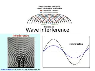
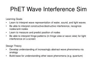
WAVE INTERFERENCE. INTERFERENCE. Interference patterns are a direct result of superpositioning . Antinodal and nodal lines are produced. These patterns can be enhanced using diffraction gratings, where all waves pass through each other from multiple point sources.

E N D
INTERFERENCE Interference patterns are a direct result of superpositioning. Antinodaland nodal lines are produced. These patterns can be enhanced using diffraction gratings, where all waves pass through each other from multiple point sources. We also learnt that the path difference for a point on a an antinodal line is always a factor of a wavelength, , whereas for a nodal line is half a wavelength, ½. Antinodal line path difference = n Nodal line path difference = n½ Where n = order 0, 1, 2, 3, …….
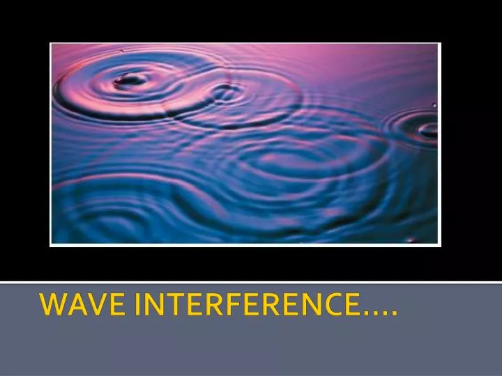
Birds eye view of 2 waves.... Red: crest meets crest Or trough meets trough. Constructive interference Blue: crest meets a trough and they cancel out. Destructive interference
Order of magnitude (m) Can be used to calculate the path difference. Whole numbers: antinodal lines Half numbers: nodal lines
Path Difference 6 wavelengths 5 wavelengths
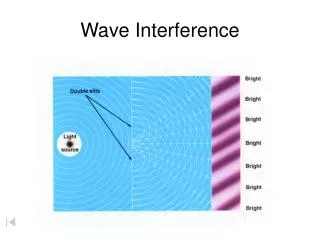
Waves interfere constructively where wavefronts meet. = antinodal lines S1 S2 Wave Intensity (Fringes) S1 and S2 are two coherent sources All points on a wavefrontare in phase with one another 2 1 n = order number Along the nodal lines, destructive interference occurs. Here antiphasewavefronts meet. 0 1 2
Young’s Double Slits A series of dark and bright fringes on the screen. Monochromatic light, wavelength l Double slit Screen
Light Double slit screen Young’s Double Slit Experiment THIS RELIES INITIALLY ON LIGHT DIFFRACTING THROUGH EACH SLIT. Where the diffracted light overlaps, interference occurs INTERFERENCE Some fringes may be missing where there is a minimum in the diffraction pattern Diffraction
A P B Assuming the sources are coherent Wave trains AP & BP have travelled the same distance (same number of l’s) Hence waves arrive in-phase CONSTRUCTIVE INTERFERENCE (Bright fringe)
Slits Screen d L d = slit separation x = fringe separation
LASER LASER Normal light sources emit photons at random, so they are not coherent. LASERS EMIT COHERENT LIGHT
Example 5: Monochromatic light from a point source illuminates two parallel, narrow slits. The centres of the slit openings are 0.80mm apart. An interference pattern forms on screen placed 2.0m away. The distance between two adjacent dark fringes is 1.2mm. Calculate the wavelength, , of the light used.
Example 5: Monochromatic light from a point source illuminates two parallel, narrow slits. The centres of the slit openings are 0.80mm apart. An interference pattern forms on screen placed 2.0m away. The distance between two adjacent dark fringes is 1.2mm. Calculate the wavelength, , of the light used. SOLUTION: The distance to the screen (2.0m) is large compared with the fringe spacing (1.2mm). The approximation formula can be used. n = dx/L [n = 1 because the fringe spacing is being calculated] = (8.0 x 10-4 x 1.2 x 10-3) / 2.0 = 4.8 x 10⁻⁷ m
Decide which points are Constructive interference and which are Destructive interference?
Interference • In phase • Out of phase By 180 deg (half a wavelength)
Youngs Double Slit Experiment • Quantum Physics. • http://www.doubleslitexperiment.com/
Changing slit separation • Double slit animation. • http://www.colorado.edu/physics/2000/schroedinger/two-slit2.html
Grating A C Monochromatic light B
Grating Several spectra will be seen, the number depending upon the value of d Second Order maximum, n = 2 First Order maximum, n = 1 White Central maximum, n = 0 First Order maximum, n = 1 Second Order maximum, n = 2 screen
n=0 Note that higher orders, as with 2 and 3 here, can overlap n=3 n=2 n=1 Note that in the spectrum produced by a prism, it is the blue light which is most deviated grating
laser 0 order 0.5m Grating 2m 2nd order Calculate the wavelength of the light.
http://webphysics.ph.msstate.edu/javamirror/ipmj/java/slitdiffr/index.htmlhttp://webphysics.ph.msstate.edu/javamirror/ipmj/java/slitdiffr/index.html