Download
1 / 21
230 likes | 423 Vues
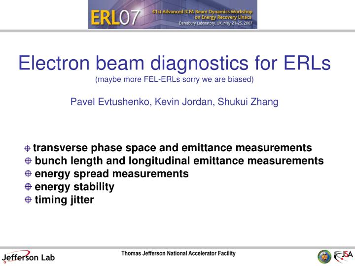
Electron beam diagnostics for ERLs (maybe more FEL-ERLs sorry we are biased) Pavel Evtushenko, Kevin Jordan, Shukui Zhang. transverse phase space and emittance measurements bunch length and longitudinal emittance measurements energy spread measurements energy stability timing jitter.

E N D
Electron beam diagnostics for ERLs(maybe more FEL-ERLs sorry we are biased)Pavel Evtushenko, Kevin Jordan, Shukui Zhang • transverse phase space and emittance measurements • bunch length and longitudinal emittance measurements • energy spread measurements • energy stability • timing jitter
Injector; transverse emittance measurements • multislit (or pepper pot) technique • well established technique • works for 10 MeV space charge dominated beam • beam profile is measured with YAG, phosphor or ceramic viewer • measures not only the emittance but the Twiss parameters as well • actually has enough information to reconstruct the phase space • has been implemented as on-line diagnostics • works with diagnostics mode only (low duty cycle, average current) • challenge: the smaller the emittance the less divergent are the beamlets – higher resolution of beam • profile measurements will be need
Injector; transverse emittance measurements But wait there is more! Measured at the JLab FEL at 270 pC When a portion of the beam has different Twiss parameters, i.e., differently positioned in the phase space it also can be see rather well. That makes life a bit more complicated, but much more interesting. The data evaluation “requires” the tomographic approach. like here, for instance (no, there is nothing wrong with the mask) • Other things to remember: • Control ghost pulses, when using photo gun • RF transients • Transverse beam stability • Alignment of the slit mask
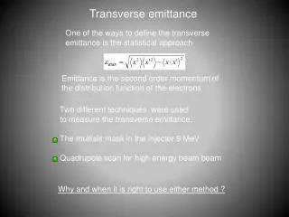
Transverse emittance measurements At high energy, beam is emittance dominated and quadrupole scan or multi screen method can be used. But it might (it does) get more complicated than that. Since a LINAC beam is not in equilibrium state, it does not have to be Gaussian. Beam propagating in a long drift space (OTR measurements)
Transverse emittance (beam profile) measurements • substantial parts of the beam have significantly different Twiss parameters • to establish the betatron match, you need to know the Twiss parameters of all parts of the beam • i.e., really-really have to do tomography • not really a problem for emittance measurements (any distribution has RMS width) • does not automatically mean a problem for the beam application (FEL) if the whole beam can be • matched to the region of use (wiggler)
sz = 90 mm Cavity on s s y y Cavity on - 180° (Streak size)2 Cavity off Asymmetric parabola indicates incoming tilt to beam Bunch length measurements with RF transverse deflecting cavity (courtesy of Patrick Krejcik, SLAC) Bunch length reconstruction Measure streak at 3 different phases 30 MW 2.4 m LoLa* An S-band DLW structure with a TM11 transverse deflecting mode at 2856 MHz *Loew, Larsen 1964
Slice emittance measurements in LCLS(courtesy of Patrick Krejcik and Paul Emma, SLAC and M. Borland APS) = meas. sim. = calc. = y distribution = actual 3-screen method LTU at 14 GeV with S-band RF-deflector at 24 MV x z x y
Transition (synchrotron) radiation is produced when the • electron bunch passes a boundary of two media • (magnetic field). • Response is prompt! Shape of the radiation pulse is a • “copy” of the electron bunch shape. • When the wave length of the radiation becomes more than • the bunch length the radiation becomes • COHERENT. ( L ) • Power is proportional to: • intensity of incoherent radiation N • intensity of coherent radiation N2 • Measurements of the radiation spectrum gives information • about the bunch length. • An interferometer is used to measure the spectrum. Bunch length measurements using coherent radiation at 135 pC N 8.4108
We use two different interferometers; essentially both are a modification of the Michelson interferometer. The two interferometers differ in implementation; Beam splitter Polarizer Detector Focusing element Mirror position measurements! Step scan & Rapid scan interferometers Modified Marin-Puplett interferometer: (step scan device 2 min/scan) beam splitter & polarizer (wire grids) detector (Golay cell) focusing (Plano-convex lens) mirror position is set by step motor Used with CTR Michelson interferometer (FTIR): (rapid scan device 2 sec/scan) beam splitter (silicon) detector (pyroelectric) focusing (parabolic mirrors) mirror position is measured by another built-in interferometer Used with CSR
raw data – interferogram Fourier transform of the interferogram Interferogram & corresponding spectrum Very short bunch 129 fs RMS and not so short bunch 384 fs RMS
Bunch length measurements using coherent radiation • Most affordable way to measure ps and subps bunches • Works with pulsed beam (tune up) as well as CW beam, essentially at any average current • Used at JLab FEL to ensure that the bunch length does not change for pulsed or CW and when the average current is increased • Ultimately needs to be setup in vacuum (or N2 purge) due to atmosphere absorption of THz • Phase information is lost – no direct bunch profile reconstruction • A detector measuring total CTR (CSR) power – a bunch length monitor
Electro-optic encoding section on ERLP courtesy of Steve Jamison encoding of bunch profile into optical pulse probe laser bunch to laser diagnostic decoding (optical pulse into profile measurement)
Benchmarking of EO diagnostics courtesy of Steve Jamison 450 MeV, 1nC~20% charge in main peak
Bench-marking of Electro-optic signal courtesy of Steve Jamison EO (temporal decoding) High resolution Lola time time
Longitudinal phase space (S. Zhang) • All reflective imagine system for the light transport • Works both with pulsed and CW beam, needs adjustable • attenuation of light and synchronized CCD camera • Planed installation in the second arc, then we can see • which part of the beam is lasing and which not! • although bunch is a bit short… Pick the visible synchrotron light from the dispersive location in the middle of the first recirculation arc.
Longitudinal phase space vs. LINAC phase (S. Zhang) S.Zhang et al., “Longitudinal Phase Characterization of Electron Bunch at the JLab FEL Facility”, Proced. 27th International FEL conference, JACowW / eCon C0508213, THPPH066, pp 740-743
(FEL shutter closed) no CSR (FEL shutter closed) CSR just starts to turn on FEL likes it here Energy spread as an FEL diagnostics no lasing • Downstream of an FEL if beam size is dominated by • dispersion • Great diagnostic of the FEL efficiency, cheap yet very • effective • Again works for pulsed and CW beam, but needs • adjustable attenuation and synced video • Also is sensitive to CSR effects: • shorter bunch stronger CSR increasedE weak lasing strong lasing
“fast” energy modulation (BPM) • BPMs has to be working not only for conventional DC or low frequency measurements but up to at least several MHz with good (adjustable) frequency resolution • At JLab FEL log-amp based BPM electronics is used in the combination with • 2.5 MS/sec and big memory buffer ADC (the resulting resolution - see the picture) • BPMs are placed in dispersive locations in the injector and downstream of the LINAC Opens up great possibilities for almost non-invasive on line diagnostics; beam based phase monitor and transfer function measurements. 10 m level 1 m level 0.1 m level
Even faster energy modulation • The fast BPMs pick up anything > 0.5m in the range up to 1.25 MHz • SRF cavities happened to have band pass mode at (1497+2.6 MHz) • This is within the klystron gain-bandwidth and LLRF can not deal with it • The result – fast energy modulation not seen by any standard diagnostic (FEL efficiency drops by 30-40%) • One solution to look • with a spectrum analyzer • at the BPM signal, but • have to sort our AM • First was detected with • the spectrum analyzer • and 50 antenna in • the RF gallery • (modulated klystron) • Also look at the spectrum of LLRF signals to find the klystron 1497 MHz 1497+2.6 MHz Tom Powers
Timing (arrival phase) jitter and its spectrum • It is important to know not only the integrated timing jitter but also its spectrum • Measurements needs to be made at very high harmonic number of the bunch frequency, even then at low timing jitter care must be taken to distinguish between • the timing jitter and AM • The need to do the measurements at different frequencies and compare spectra to see that is AM and that is phase variation • Current (pill box) cavities provide ample signal but do not enable the measurements at different frequencies, stripline BPM signals are broad band but need amplification Looks like 150 fs RMS from 10 Hz to 1 MHZ, but these are AM 50 fs RMS from 10 Hz to 1 MHZ
Conclusion • This talk is meant as an intro to the working group session 4 – Please join us! • Many of the existing diagnostics can be used but needs to be taken to more sophisticated level (from beam size measurements to x-x` tomography) • Whole phase space measurements (not only its projections) for both the transverse and longitudinal phase space still needs more work • BPM systems need to be, not only high resolution, but also capable of seeing beam motion at high frequency (What is the high frequency? Determine on this workshop.) • Multi pass BPMs are really needed as well as beam profile measurements in the LINAC with two beams • I wish also to discuss procedures – which may surprise those who know me! • There are still many challenges, so we have this workshop & possibly our jobs • FEL Quad.mov