Download
1 / 47
470 likes | 771 Vues
Deployment of VoIP in Data Networks. Dr. Khaled Salah salah@kfupm.edu.sa. OPNET Simulation. To deploy VoIP in Data Networks. Outline. OPNET Model VLAN Configuration Generation of background traffic Generation of VoIP traffic Discussion of simulation results Assessing network health

E N D
Deployment of VoIP in Data Networks Dr. Khaled Salah salah@kfupm.edu.sa
OPNET Simulation To deploy VoIP in Data Networks
Outline • OPNET Model • VLAN Configuration • Generation of background traffic • Generation of VoIP traffic • Discussion of simulation results • Assessing network health • VoIP Readiness Assessment • A new product from OPNET K. Salah
Introduction • OPNET contains a vast amount of models of commercially available network elements, and has various real-life network configuration capabilities. • This makes the simulation of real-life network environment close to reality. • Other features of OPNET include GUI interface, comprehensive library of network protocols and models, source code for all models, graphical results and statistics, etc. • There is no formal or known approach or methodology in how OPNET can be used to assess the support and readiness of an existing network in deploying VoIP. • Goal is to predict, prior to the purchase and deployment of VoIP equipment, the number of VoIP calls that can be sustained by an existing network while satisfying QoS requirements of all network services and leaving adequate capacity for future growth. K. Salah
Simulation Approach • The approach can be applicable to the successful deployment of any multimedia application such as VoIP and videoconferencing. • We focus on VoIP as the new service of interest to be deployed. • Issues to address: • Characteristics of VoIP traffic and QoS requirements • VoIP flow and call distribution • Defining future growth capacity • Measurement and impact of background traffic. • As a case study, we illustrate how our approach and guidelines can be applied to a typical network of a small enterprise. K. Salah
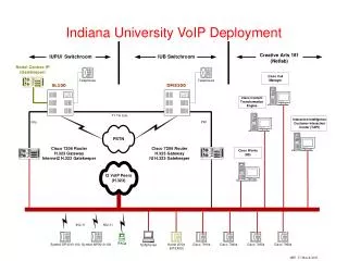
Case Study K. Salah
Network Elements • The network is Ethernet-based and has two Layer-2 Ethernet switches connected by a router. • 3Com superstack3 3300 Ethernet switch • The router is Cisco 2621, and the switches are 3Com Superstack 3300. • The network makes use of VLANs in order to isolate broadcast and multicast traffic. • A total of five LANs exist. All VLANs are port based. • Switch 1 is configured such that it has three VLANs. • VLAN1 includes the database and file servers. • VLAN2 includes Floor 1. • VLAN3 includes Floor2. • Switch 2 is configured to have two VLANs. • VLAN4 includes the servers for E-mail, HTTP, Web & cache proxy, and firewall. • VLAN5 includes Floor 3. • All the links are switched Ethernet 100Mbps full duplex except for the links for Floor 1, Floor 2, and Floor 3 which are shared Ethernet 100Mbps half duplex. K. Salah
New Topology with VoIP Components K. Salah
Changes to VLANs • It is proper to include the gatekeeper to be a member of VLAN1 of Switch 1 which includes the database and file servers. • This isolates the gatekeeper from multicast and broadcast traffic of Floor 1 and Floor 2. • In addition, the gatekeeper can access locally the database and file servers to record and log phone calls. • On the other hand, we create a separate VLAN for the gateway in order to isolate the gateway from multicast and broadcast traffic of Floor 3 and the servers of switch 2. • Therefore, the network has now a total of six VLANs. K. Salah
OPNET Model K. Salah
VoIP gateway is modeled as an Ethernet workstation • The gatekeeper signaling traffic is ignored, and hence modeling such and element and its traffic is not taken into account as we base our study on the worst case situation. K. Salah
Floor subnet Model • Floor LANs have been modeled as subnets that enclose an Ethernet switch and three designated Ethernet workstations used to model the activities of the LAN users • One of these workstations generates the background traffic of the floor while the other two act as parties in VoIP sessions. • F1_C1 is a source for sending VoIP calls. F1_C2 is a sink for receiving VoIP calls. • F1_C3 is a sink and source of background traffic. K. Salah
Note that the model of floor LANs does not represent precisely the floor multimedia PCs or IP phones. • However, building a model with such exact floor network configurations will make simulation very tedious. • This is because it requires for each time a new VoIP call (or a group of calls) is added to perform two tasks: first adding individual PCs with individual profiles and settings, and then running the simulation. • This has to be repeated manually and results have to be examined after each simulation run. • One simulation run can take up to 15 hours. K. Salah
Fundamental Ideal of Approach • Our simulation approach is an automated one. • The simulation is configured to automatically keep generating three calls every three seconds. • After some time, check • The health of network elements • VoIP QoS (delay and packet loss) • As we add calls incrementally to the network, monitor the thresholds or bounds for VoIP delay and network capacity or bandwidth. When any of these bounds has been reached, the maximum number of calls can then be known. • Note that the bound for network bandwidth is reflected in seeing packets being lost or observing a mismatch between VoIP traffic being sent and received. K. Salah
Component Configuration and Growth Factor • In all of our configurations, we reserve 25% of the capacity of each network component for future growth. • The Router. The main parameter to be set in the router configuration is the forwarding rate. In our network, Cisco 2621 router has a forwarding rate of 25,000 pps. However, since we consider a 25% growth factor, the effective forwarding rate of the router is set to 18,750 pps. • The Switches. Similarly, the main parameter to be configured in all the switches is the switching speed, which is 1.3M pps for the 3Com Superstack3 3300 switches. With a growth factor of 25%, the effecting switch speed is set to 975,000 pps. • The Links. For each link in the network model, a background utilization of 25% has been introduced to account for the growth factor. K. Salah
VLAN Configuration • In OPNET, VLANs are implemented based on ports, i.e. it is required to associate each port with its VLAN. • One port can belong to exactly one VLAN. • If a port is required to carry the traffic of multiple VLANs, it must be defined as an Untagged Trunk Link in the switch’s VLAN port configuration table. • It is worthy to note that port 12, which is connected directly to the router, is described as an Untagged Trunk Link since it carries the traffic of all VLANs to the router, which routes it to the destination VLAN. K. Salah
Modeling Background Traffic • Traffic measurement are represented in a spreadsheet with a certain format • Import spreadsheet to OPNET via Traffic/Import Conversation Pairs • Since we considered symmetric background traffic for egress and ingress, the entries for the traffic values reflected in the spreadsheet are duplicates. K. Salah
Modeling VoIP Traffic • Predefined application for VoIP but needs to be configured properly using Application Definition • In OPNET terminology, a voice frame is a collection of 32 voice samples of which each sample is 8 bits, i.e. each voice frame is 32 bytes in size. However, in the standard we are adopting, each VoIP packet has a payload of 160 bytes. Hence we set Voice Frames per Packet attribute to 5. • The third attribute to which attention should be paid is the Symbolic Destination Name. As will be discussed shortly, this symbolic name is used in defining the destination nodes for VoIP calls. K. Salah
VoIP Application Profile • After defining and configuring the VoIP application, it is required to configure the way in which workstations will be implementing this application. • We do this via Application Profile • The floor subnet workstations, designated for generating VoIP calls, will be configured to support this profile, namely • F1_C1, F2_C1, and F3_C1. K. Salah
In these figures, we let the Start Time Offset of the VoIP traffic to start after 60 seconds and for the first VoIP call to start after 10 seconds. • This means that the first VoIP call will produce traffic after 70 seconds from the start of the simulation run. • By default in OPNET, the background traffic starts after 40 seconds. • To keep generating calls, the repeatability of the VoIP application is set to be Unlimited with an inter-repetition time of 2 seconds, as shown. K. Salah
Generation of calls • So effectively, • The VoIP traffic starts at 70 seconds at which a total of 3 VoIP bi-directional calls are initially added. Then, every 2 seconds 3 VoIP calls are added. • So look at the simulation time of min minutes and sec seconds • The total number of calls can be supported is given by this formula as K. Salah
Generating VoIP Traffic Based on Call Distribution • The floor subnet workstations of F1_C1, F2_C1, and F3_C1, designated for generating VoIP calls, are configured to support the VoIP_Profile. • Destination of C1 is “Symbolic Name” of VoIP_Dest • Added in the Application: Destination Preferences table of each C1 • Distribution is done via Actual Namewith selection weight (out of 9) • We set the IP processing rate for each workstation to infinity. • We are interested in the performance network core only, and not the edge clients K. Salah
Need to normalize the weight • Make them all out of 27 • Note that intra-floors need to be divided by 2 • F1-F2 is 2/27 divided by 2 1/27 K. Salah
Simulation Results • Choose individual statistics globally for VoIP traffic, and locally for router, switches, and links • Remember • The generation of background traffic, by default in OPNET, started at 40 seconds from the start time of the simulation run. • The VoIP traffic started at 70 seconds at which a total of 3 VoIP bi-directional calls are initially added. Then, every 2 seconds 3 VoIP calls are added. • Total calls are given by • The Simulation stops at 8 minutes in which a total of K. Salah
Interpretations of traffic load • The total VoIP traffic generated by the end of simulation run is very close 61,500 pps. • In fact, simulation results gave 61,429 pps. • Calls to be supported can be determined two ways when mismatch happens: • Examine Y axis • Traffic volume of 33,000 pps or 330 VoIP calls • Examine X axis K. Salah
Interpretations of delay • Delay should not exceed 80 ms • The delay stays less than 80 ms until a simulation time of 4 minutes and 54 seconds at which the delay increases sharply. • Hence, the number of calls can be computed as calls K. Salah
Conclusion • The number of voice calls to be supported by the network is bounded more by the network bandwidth than the delay. • Hence, the number of the VoIP calls that the network can support based on simulation is 330 calls. K. Salah
Router K. Salah
Router Switch links K. Salah
Floor subnet edge links K. Salah
Simulation Environment and Accuracy • The elapsed time for the simulation run was approximately 15 hours and produced 722 million events, executed at average speed of 13878 events/second. • Sun E450 server with a SPARCV9 400 MHz processor and 1G bytes of memory, and Solaris 7 OS • It is possible to cut down on the simulation run time: • configure the generation of more calls simultaneously at the start of the simulation, say 300 calls, and then add more calls slowly at a rate of 3 calls every 2 seconds. • stop the simulation at earlier time, say at 6 minutes instead of 8 minutes. • In order to gain accuracy (with a narrow confidence interval) of our simulation results, following DES guidelines, at least five simulation replications ought to be run by feeding OPNET with different initial seeds. • OPNET’s pseudo random number generator is based on BSD’s algorithm which permits safely, i.e., with no concern of overlapping of random number streams, any integer value to be an initial seed. K. Salah
Final Simulation Run • Based on the simulation results, the existing network can support 330 VoIP calls while satisfying the VoIP QoS of throughput, latency and packet loss. • In earlier runs, the voice calls were added every 2 seconds and the simulation was not allowed to stabilize for a long time. • Our attention was focused on finding out the number of voice calls that the network can sustain. • As a final check to ensure a healthy network and a normal behavior for all network elements, we perform a final simulation run in which 330 voice calls are added, all at once at the start of the simulation, say after 70 seconds. • We let the simulation run execute for a prolong amount of time, say good 5 minutes, to reach a steady state. Then we examine the health of each network element. • In our example, this simulation run of supporting 330 calls was not successful. The simulation run showed a mismatch between traffic sent and received and a delay of more than 80 ms • A successful simulation run of 306 voice calls showed normal and healthy results with no packet loss, end-to-end delay of 2.25 ms, and adequate utilization of router and switch CPUs and links. K. Salah
Repeatability table to generate 306 calls • Figure shows how to configure the generation of 303 concurrent calls, after the first initial 3 calls get generated. • Each VoIP application profile for the designated sending workstations of the three floors has to be configured as shown. K. Salah
Concluding Remarks • The network capacity to support VoIP is bounded more by the network throughput than the delay. • The existing network, with a reserved growth factor of 25%, can safely support up to 306 calls while meeting the VoIP QoS requirements and having no negative impact on the performance of existing network services or applications. • The primary bottleneck of the network is the router. If the enterprise under study is expected to grow in the near future, i.e., more calls are required than 306 calls, the router replacement is a must. The router can be replaced with a popular Layer-3 Ethernet switch, and thus relieving the router from routing inter-floor calls from Floor 1 to Floor 2. K. Salah
VoIP Readiness Assessment from OPNET • Allows to • Determine network capacity required for VoIP Deployment • Ensure the performance of existing applications • Optimize QoS configuration • Define device configuration to support VoIP and Qos • Predict the call quality • Re-design the network to support voice • Resize links to address capacity issues K. Salah