Download
1 / 27
280 likes | 529 Vues
AVR Coding on OPTIMUS. - A Development board deveoped by Electronics Club, IIT Bombay Contact : Rahul Prajapat (9892945399) r ahul.prajapat9@gmail.com. Content :. OPTIMUS overview Software and Driver installation Atmega32u4 pin diagram Pin mapping on Optimus

E N D
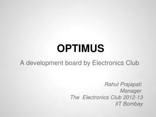
AVR Codingon OPTIMUS - A Development board deveoped by Electronics Club, IIT Bombay Contact : Rahul Prajapat (9892945399) rahul.prajapat9@gmail.com
Content : • OPTIMUS overview • Software and Driver installation • Atmega32u4 pin diagram • Pin mapping on Optimus • Compiling and Programming • Codes : • Blinking an led : blink.c • Analog to Digital converter : adc.c • PWM : pwm.c • UART : uart.c References
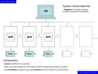
OPTIMUS overview • Brain– Atmel’s Atmega32u4 microcontroller • Peripherals on it : • USB programmable • Motor Driver • Slot for servo motors • Xbee Shield • I/O Expander • LCD Shield • Serial Communication • Xbee shield
Contd.. IC's used : ATMEGA32U4 - Atmel based • TB6612FNG - Toshiba's motor driver IC • PCF8575 - TI based 16 bit I2C I/O expander • Ft232 - FTDI chip • LD29150DT50R - 5V voltage regulator • TLV2217-33 - 3.3V voltage regulator (This also can be used - LD29150DT33R) Optimusdocumetation : Stab-iitb.org/wiki/optimus • User manual of the "Optimus" : http://stab-iitb.org/electronics/optimus.pdf • How to code : http://stab-iitb.org/electronics/how_to_code_optimus.pdf • Datasheet of Atmega32u4 : http://stab-iitb.org/electronics/atmega32u4.pdf
Software and Driver installation : • WinAVR : http://sourceforge.net/projects/winavr/files/ • Atmel FLIP: http://www.atmel.com/tools/flip.aspx • Libusb driver: http://sourceforge.net/projects/libusb-win32/
What is a microcontroller? • It is essentially a small computer • Compare a typical microcontroller (uC) with a typical desktop
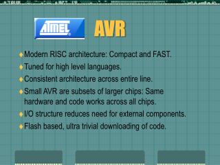
Microcontroller Families • 8051 (Intel) • PIC (Microchip) • AVR (Atmel) • MSP430 (TI) • ARM (ARM)
Why use a micro-controller? • It is programmable. It is fun. • A code (typically written in C) decides what it does • Easier to write a code than design and make a custom circuit for complex jobs • e.g. In a micromouse, a single uC controls the motors, finds distance from the walls, explores and solves the maze • The same muC can be used in hundreds of applications
Hello world • Turning on a led : #include<avr/io.h> void main() { DDRB = 0xff; PORTB = 0x00; }
Compiling and Programming • Save the code as gpio.cin a separate folder (not strictly necessary, just a good practice) • Create a makefile using Mfile and save in the same folder • Open it in Winavr Programmer’s Notepad and change: ◦ Line 44: MCU = atmega16 ◦ Line 65: F_CPU = 1000000 ◦ Line 73: TARGET = blink, Line 83: SRC = $(TARGET).c ◦ Alternatively, TARGET = anything_you_want and SRC = blink.c ◦ Line 281: AVRDUDE_PORT = usb • In Programmer’s Notepad, Tools > Make All to compile • Connect USB to computer and Optimus • Go to Flip • File -> Load hex file • Device -> select -> atmega32u4 • Settings -> communication -> usb -> open
Blinking an led : • Choose a port and a pin • In the code Loop { 1. Set pin direction to output 2. Set pin output to high 3. Wait for 250ms 4. Set pin output to low 5. Wait for 250ms }
blink.c #include<avr/io.h> #include<util/delay.h> void main() { DDRC=0xff; while(1) { PORTC=0xff; _delay_ms(200); PORTC=0b00000000; _delay_ms(200); } }
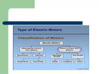
Analog to Digital converter • Applications – Music recording, Radar etc • Most of the sensors are analog -temperature, pressure, pH, light intensityetc Sampling : Resolution, Saturation
Analog to Digital converter • Converts an analog voltage VIN to a digital number • ADC_Data • 10-bit conversion result • Conversion time = 13.5 * ADC clock period • Up to 15k conversions per sec • 12 channels
Analog to Digital converter • Data registers : • ADC Control and Status Register : • ADEN: This bit turns on the ADC when set. • ADPS2/1/0: prescalar; In our case, this division factor is 128. This implies that the frequency for our ADC is 16MHz/128 = 125kHz • ADSC: This bit, when set starts the conversion. Once the conversion is done, it becomes low automatically. • ADIE: When this bit is set (and the I-bit in SREG* is set), the ADC Conversion Complete Interrupt is activated
Adc.c #include <avr/io.h> #include <avr/interrupt.h> #include <stdlib.h> #include <util/delay.h> volatile float sl=0; void adc_init(void){ ADCSRA |=((_BV(ADPS2))|_BV((ADPS1))|_BV((ADPS0))); ADMUX |= _BV(REFS0); ADCSRA|=_BV(ADIE); ADCSRA |= _BV(ADEN); } void port_init(void) { DDRF=0x00; PORTF=0x00; DDRC = 0xff; PORTC = 0x00; }
Contd… void main() { port_init(); adc_init(); sei(); ADCSRA |= _BV(ADSC); while (1) { ADCSRA |=_BV(ADSC); _delay_ms(10); } } ISR(ADC_vect) { sl = ADCL + ADCH*256; if(sl>512){ PORTC=0xff;} else{PORTC = 0x00;} }
PWM • Fast PWM mode :
PWM.c #include<avr/io.h> #include <avr/interrupt.h> volatile float sl=0; void adc_init(void){ ADCSRA |= _BV(ADPS0)|_BV(ADPS1)|_BV(ADPS2); ADMUX |= _BV(REFS0); ADCSRA |= _BV(ADEN); } void port_init(void) { DDRF=0x00; PORTF=0x00; DDRB=0xff; PORTB = 0X00; }
Contd… int main(void) { port_init(); //* no of timers TCCR0A |= _BV(WGM00) | _BV(WGM01) | _BV(COM0A1); //* diff fast pwm, n other modes TIMSK1 |= _BV(TOIE0); //*where r we starting the counting ? adc_init(); sei(); TCCR0B |= _BV(CS01) | _BV(CS00) ; //* timer clock source/64 --> datasheet ? ADCSRA |= _BV(ADSC); while(1){ ADCSRA |=_BV(ADSC); sl = ADCL+ADCH*256; OCR0A = (sl/1023)*256; sl=0; } return(0); }
Uart.c void USART_Init( void ) { UCSR1A = 0; UCSR1B = (1<<RXEN1) | (1<<TXEN1); UCSR1C = (1<<UCSZ10) | (1<<UCSZ11); UBRR1L = BAUD_PRESCALE; // Load lower 8-bits of the baud //rate value into the low byte of the UBRR register UBRR1H = (BAUD_PRESCALE >> 8); // Load upper 8-bits of the baud //rate value into the high byte of the UBRR register /* Enable receiver and transmitter */ UCSR1A &= ~(1 << U2X1); }
Contd… void USART_Transmit( unsigned char data ) { /* Wait for empty transmit buffer */ while ( !( UCSR1A & (1<<UDRE1)) ); /* Put data into buffer, sends the data */ UDR1 = data; } unsigned char USART_Receive( void ) { /* Wait for data to be received */ while ( !(UCSR1A & (1<<RXC1)) ); /* Get and return received data from buffer */ return UDR1; }
Resources and Links • Tutorials and sample codes: 1. http://www.avrtutor.com 2. http://winavr.scienceprog.com 3. http://kartikmohta.com/tech/avr/tutorial • ChiraagJuvekar • Atmel application notes: projects, tutorials, code examples, miscellaneous information • http://www.atmel.com/dyn/products/app_notes.asp?family_id=607 • Forums: http://www.avrfreaks.net • Advanced projects: 1. http://instruct1.cit.cornell.edu/courses/ee476/FinalProjects 2. http://www.obdev.at/products/vusb/projects.html