Download

1 / 39
400 likes | 519 Vues
Magnetometer Testing Board. Presented by Jianer Shi 04/25/2011. Sections. Sections. Background Board Design Code 2.1 Microcontroller 2.2 Graphic User Interface (GUI) From here on…. Section 1/4. Background. Background.

E N D
Magnetometer Testing Board Presented byJianer Shi 04/25/2011
Sections • Background • Board Design • Code 2.1 Microcontroller 2.2 Graphic User Interface (GUI) • From here on…
Section 1/4 Background
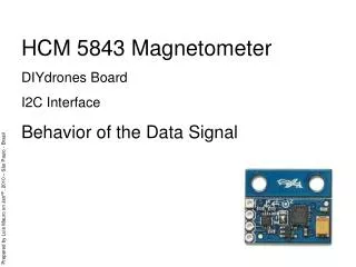
Background • Toque coil is used to produce a magnetometer dipole which controls the satellites attitude. • In order for the toque coil to behave as expected, an accurate measurement of magnetic field is required. • Magnetometer is an essential part to determine the earth magnetic field
Background • Previous testing done by Ryne Beeson in 2009 shows noise of 0.02 Gauss, which is unacceptable for accurate attitude determination and control. Further testing is suggested and a magnetometer testing board is built for easy testing and lower electronic noise.
Section 2/4 Board Design
Board Summary PCB Laying Tool: Eagle 5.11.0 Microcontroller: PIC18F2221-I Communication Port: Mini – USB B Power: Mini-USB 5V Crystal Oscillator: 11.0592Mhz UART Communication Baud Rate: 57600 Communication: Serial-USB (FT232RL)
Design Criteria • Microcontroller • Support I2C • Support UART • Communication • Error tolerance • Board • Small size • Mountable • User Interface • Able to pool and save Matlab friendly data for later process
Microcontroller • PIC18F2221-I • Minimum Pin Number to satisfy the requirement • Small size (SOIC Package) • Has 1 UART and 1 I2C • 5V Power Supply from USB • Errata page provided by manufacturer has no significant problem with UART and I2C • Compare to other Microcontrollers, this is the minimum one satisfies the design criteria.
Power and Communication • Mini-Usb Port • Small size • Provide both 5V power and communication • FT232RL USB-Serial Chip • Provide 3.3V output - eliminate 2 voltage regulators and has 500mA cutoff current protection • Provide UART to USB link
Crystal Oscillator • 11.0592Mhz • This choice will resulte in 0% error with a wide range of baud rate choice. • We choose 57600 baud rate
Section 3.1/4 Microcontroller code
I2C • Communication between magnetometer and microcontroller • Library provided by i2c.h and pic18f2221.h from C18 Compiler
Magnetometer I2C • Slave address (0x32) for write (0x33) for read
Magnetometer I2C • Functions (0x40) Accelerometer Data of 3 axis (0x45) Magnetometer Data of 3 axis (0x50) Heading Data of 3 axis (0x55) Tilt Data of 3 axis Return value: 6 byte, 2 byte per axis (in hex: xxxx) (0x82) Reset the processor, no return value
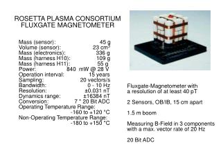
Magnetometer Spec • 500ms power up delay before extract data • 1ms delay for each read
3.3V to 5.5VI2C Logic Level Conversion • Logic Level conversion is necessary because components operate on different power Magnetometer3.3V Microcontroller5V
3.3V to 5.5VI2C Logic Level Conversion Source: <Bi-directional level shifter for I²C-bus and other systems. Philips>
UART • Library • Usart.h • 2 Pins • TX for sending • RX for receiving
Serial Protocol In order to send information that the computer side can decode, all information pulling from the magnetometer is sent through a protocol (in hex) (eeeeeeee) (00) (function 1 byte xx)(data 2 byte xxxx)(ffffffff)
Serial Protocol (eeeeeeee) (00) (function 1 byte xx)(data 2 byte xxxx)(ffffffff) • (eeeeeeee) starting flag • (ffffffff) end of line • (00) There are still new function data to be transferred
Serial Protocol (eeeeeeee) (00) (function 1 byte xx)(data 2 byte xxxx)(ffffffff) Functions (41) Accelerometer X (42) Accelerometer Y (43) Accelerometer Z (46) Magnetometer X (47) Magnetometer Y (48) Magnetometer Z (56) Tilt X (57) Tilt Y (58) Tilt Z (51) Heading X (52) Heading Y (53) Heading Z
Section 3.2/4 Graphical User Interface(gui)
GUI Programing Language • Python • Pyserial • wxtools • Qt4 • Matplotlib • Toolchain • Pyqt4
Python • State Machine to decode protocol • 24 State to decode serial protocal • Error Tolerance imbedded even though the UART will in theory result in 0% communication error
Data Saving Button • All raw data will be saved in a tabular format, This can be easily imported into a matlab vector. • Button to control start saving data and stop saving data • Reason to keep raw data • Decimal data will result Matlabunderrun (not enough precision)
Real Time Plot • Based on the open source code developed by Eli Bendersky • 3 colors to display the 3 axis data on the same graph simultaneously
Section 4/4 From here on ...
From here on • The board will handed over to whoever is going to test the magnetometer • Since the GUI has been revised many times for easy testing, the tester will find the whole system easy to use and test