Download
1 / 1

E N D
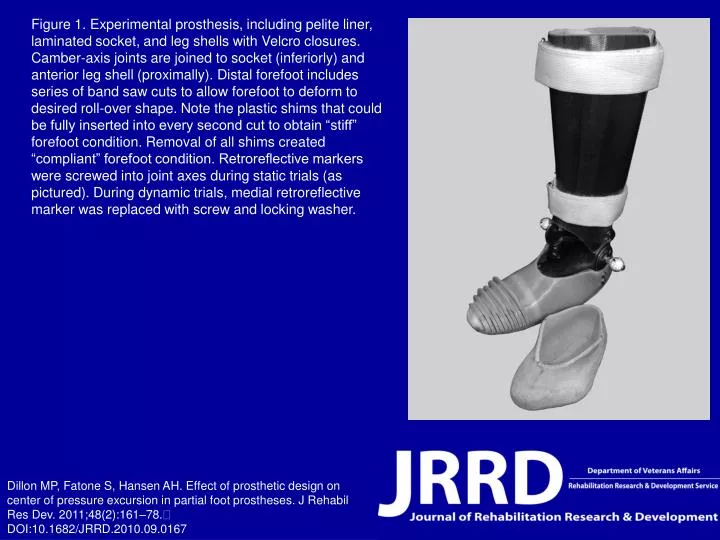
Figure 1. Experimental prosthesis, including pelite liner, laminated socket, and leg shells with Velcro closures. Camber-axis joints are joined to socket (inferiorly) and anterior leg shell (proximally). Distal forefoot includes series of band saw cuts to allow forefoot to deform to desired roll-over shape. Note the plastic shims that could be fully inserted into every second cut to obtain “stiff” forefoot condition. Removal of all shims created “compliant” forefoot condition. Retroreflective markers were screwed into joint axes during static trials (as pictured). During dynamic trials, medial retroreflective marker was replaced with screw and locking washer. Dillon MP, Fatone S, Hansen AH. Effect of prosthetic design on center of pressure excursion in partial foot prostheses. J Rehabil Res Dev. 2011;48(2):161–78. DOI:10.1682/JRRD.2010.09.0167