Download
1 / 5
50 likes | 147 Vues
Calibration and monitoring system for FPD. to check the response of the MAPMT and L0PMT as it involves in time ( + to see if we have any dead channels + compare the response of the individual channels ?) LMB (light mixing box) – LEDs inside; after the LED receives

E N D
Calibration and monitoring system for FPD • to check the response of the MAPMT and L0PMT • as it involves in time ( + to see if we have any dead channels • + compare the response of the individual channels ?) • LMB (light mixing box) – LEDs inside; after the LED receives • the electric pulse it emits the light which is transmitted via optical • fibers into MAPMT (L0PMT)
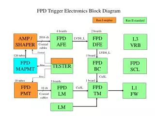
LMB – light mixing box FPD has 5 LMBs (dip – 36 fibers; A1,A2,P1,P2 – 64 fibers each) 3m long round 1mm SLP pulse PIN power (+6,-12V,ground) PIN out
SLP pulse The SLP pulse will be generated by the special VME boards. These boards are in the moveable counting house. The pulse will be send via the long green signal cables to our LMBs in the tunnel. The leading edge of this pulse should be sharp (5-15?ns) after the long cable to be able to produce light.
Cartridge • MAPMT calibration: - 16 LMB fibers per cartridge - each LMB fiber is connected to the bunch of 8 250mm fibers - each of these little fibers goes to one MAPMT channel (there are glued into the cookies) • L0PMT calibration: - make another hole and use the spare LMB fibers
1 – PIN out (use the spare AMP board, ribbon cable, AFE board) ? 2 – PIN power (+6V,-12V,ground – from AMP power supply) 3 – SLP 4 – ribbon cables 5 – optical fibers 6 – flat cables (between MAPMT and AMP) Layout