Download
1 / 28
280 likes | 395 Vues
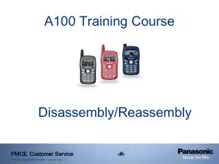
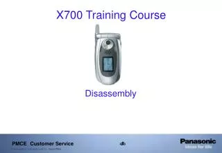
RF Description. X700 Training Course. RF component Identification. RF Receiver Service Training. This section shows the assembly drawing of the PA section. It contains the PA, ASM, Limiter Amplifier, and 900MHz TX BPF. RF Receiver Service Training.

E N D
RF Description X700 Training Course
RF Receiver Service Training This section shows the assembly drawing of the PA section. It contains the PA, ASM, Limiter Amplifier, and 900MHz TX BPF.
RF Receiver Service Training This section shows the assembly drawing of the receiver section. It contains the TRX IC, 900/1800/1900MHz RX BPFs, VCTCXO, and TX Harmonic filters.
RF Receiver Service Training This section shows the circuit diagram of the Receiver and its components.
The X700 is a tri-band device. The operational frequencies (RX), channel numbers, and the power level are shown below. [This section is intended to provide the general information on GSM]. EGSM 900MHz Frequency Range= 925MHz – 960MHz Channel Number = 975 -1023 and 0-124 Ch 975(low) = 925.2MHz; Ch 38(center) = 942.6MHz and Ch 124(High) = 958.8MHz TX Power level = PCL 5 (Highest) and PCL 19 (Lowest) DCS 1800MHz Frequency Range = 1805MHz – 1880MHz Channel Number = 512 - 885 Ch 512(low) = 1805.2MHz; Ch 698(center) = 1842.4MHz and Ch 885(high) = 1879.8MHz TX Power level = PCL 0 (Highest) and PCL 15 (Lowest) PCS 1900MHz Frequency Range= 1930MHz – 1990MHz Channel Number = 512 - 810 Ch 512(low) = 1930.2MHz; Ch 661(center) = 1960MHz and Ch 810(high) = 1989.8MHz TX Power level = PCL 0 (Highest) and PCL 15 (Lowest) RF Receiver Service Training
RF Receiver Service Training The following circuitry shows ASM’s voltages and signal levels assuming a -50dBm input signal at the antenna port.
RF Receiver Service Training The table on the left shows voltage conditions based on the selected band for the antenna switch module (In RX mode). High = 2.7V Low = 0.3V The voltages on the other RF pins and the antenna pin should be 2.2V and all other pins should be 0V when any of the band is configure.
RF Receiver Service Training This section shows the voltages and the signal levels at the input and output of the RX BPF. (The level at the differential port of the BPF may be lower than what it is specified below).
RF Receiver Service Training The following circuit diagram shows signal levels and the voltages for the transceiver IC.
In order to check the voltages and signal levels, the unit has to be placed in non-signaling mode using PhoneTool. The commands to place a unit in a non-signaling RX mode are as follows. Turn the device ON. Connect the USB data cable to the serial port. Open PhoneTool (the main page will have general information about the SW and operational band). Use the pull down menu under “Mode” and select Non-Signaling mode option. Click on the Non-Signaling mode box. Type the channel number to be tested in ‘RX” box and hit Enter (This box is under the ARFCN block). [Use the appropriate frequency/channel mentioned earlier in this presentation] Note: You must Hit Enter after the channel is set. Under “PA Level” block, enter appropriate power level (for 900 = 5 and 1800/1900 = 0) and hit Enter. Under “GMSK mode”, click on Random box. Under TSC box, use pull down menu and select 0. Under “RF Mode”, select “RX” Cont section. Inject the RF signal at the appropriate frequency and power level at the antenna port. After each command, check the command display box in the PhoneTool screen for “OK”. If “OK” is not displayed, turn the device off and repeat the above steps. The order in which these commands are sent is very important. If the unit doesn’t work the first time, power off the device and repeat the steps. To see the Data, Clk, and En signal, select “RX” Burst for step 8 under RF Mode. RF Receiver Service Training
RF Receiver Service Training The following screen shot shows what the PhoneTool window looks like when all the necessary commands are send.
Also, it will be helpful to check RX IQRMS for RX troubleshooting. This can be done by placing the unit in non-signaling mode and following steps 1-7 mentioned earlier in PhoneTool. After sending all of these commands, send following. 8) Under “RF Mode”, select “RX” under Burst . 9) Use the pull down arrow for RX(1) under “Gain” section and select “69”. (Do not Hit Enter) 9) Apply -90.5dBm RF level at the antenna port (GSM modulated) [Alternatively, a CW signal may be used but should be offset by 68kHz from the center channel] 10) Check box next to poll select under “RX IQRMS” section. “Slot 1” should show RX level of ~800-900. The PhoneTool window will look like as follows. RF Receiver Service Training
RF Receiver Service Training The following diagram shows the setup needed to troubleshoot non functional units.
Helpful Hints: 1) Unit is drawing more current: Check VRF1 to see if it is shorted using multimeter. If it is, check TX Harmonic filters (FL500 and FL501). 2) Unit fails RX calibration: Check RX IQRMS with a -90.5dBm signal. RX IQRMS should be between 800 and 900. If it is less than 800, there is too much loss in the RX path. If the unit also failed TX cal, check ASM and RF connector. If the unit passed TX cal, check RX BPF. 3) Unit fails RX fast bit error rate check (FBER) during RF parametric testing: If unit passed RX cal, check the ASM and the RF connector. RF Receiver Service Training
RF Transmitter Service Training PA section assembly drawing. This section contains the PA, ASM, Limiter Amplifier, and 900MHz TX BPF.
RF Transmitter Service Training Transceiver section assembly drawing. This section contains the TRX IC, RX BPFs, VCTCXO, and TX 3rd Harmonic filters.
RF Transmitter Service Training Transceiver IC and VCTCXO circuit diagram.
RF Transmitter Service Training 3rd Harmonic filter and Limiter Amplifier circuit diagram.
RF Transmitter Service Training Tx SAW filter and PA circuit diagram.
RF Transmitter Service Training ASM circuit diagram.
RF Transmitter Service Training The table on the left shows voltage conditions based on the selected band for the antenna switch module (In TX mode). High = 2.7 V Low = 0 V
RF Transmitter Service Training E-GSM 900 MHz Band Output Power Levels
RF Transmitter Service Training DCS 1800 MHz Band Output Power Levels
RF Transmitter Service Training PCS 1900 MHz Band Output Power Levels