Download
1 / 23
240 likes | 442 Vues
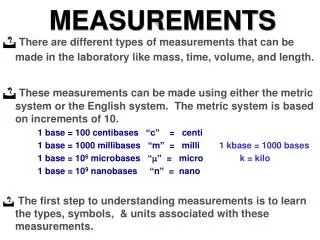
DC Measurements. Module-1. Objectives. Define voltage and give its unit of measurement. Identify the two different types of voltmeters. Connect a voltmeter in a circuit to measure voltage. Use a digital multimeter to measure voltage. Define current and give its unit of measurement.

E N D
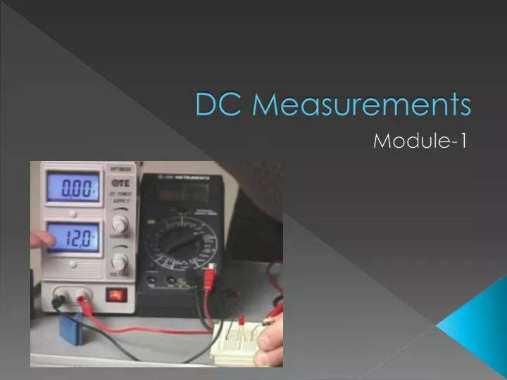
DC Measurements Module-1
Objectives • Define voltage and give its unit of measurement. • Identify the two different types of voltmeters. • Connect a voltmeter in a circuit to measure voltage. • Use a digital multimeter to measure voltage. • Define current and give its unit of measurement. • Connect an ammeter in a circuit to measure current. • Use a digital multimeter to measure current. • Define resistance and give its unit of measurement. • Determine the resistance value using the resistor color code chart. • Use a digital multimeter to measure resistance.
Module Contents Topic Page No. 1.1 Introduction 4 1.2 Voltage Measurement 5 1.3 Current Measurement 8 1.4 Resistance Measurement 11 1.5 Lab Activity 1 13 1.6 Lab Activity 2 16 1.7 Module Exercise 17
Introduction • wall outlet/power socket Batteries
There are two types of voltages • DC: Direct Current In DC, the flow of electric charge is only in one direction. DC is Produced by a battery and is used to power portable devices such as the • cell phones, • iPods, etc. • AC: Alternating Current In AC, the flow of electric charge periodically reverses direction. AC Is generated in a powerplant and is delivered to the electric outlets in your home and buildings. • Washing machines, • television, • water • heater etc. operate on ac. • Note: See Video
DC • Devices Sources- Solar Panel
AC • Device Source – Power Plant
Voltage • Voltage is the electric force that drives current around an electric circuit. • Unit of voltage is volt, • Symbol is ‘V’.
Voltage Measurement A voltmeter is used to measure voltage. There are two types of voltmeters Analog Voltmeter Digital Voltmeter
Multimeter • The analog multimeter measures voltage by deflecting a needle against a scale. • A digital multimeter displays the voltage value in digits. • Note: Voltage and other electrical quantity may also be measured using a digital multimeter (DMM)
Steps for Measuring voltage • Set the multimeter knob to read voltage (dc or ac) and select the range. • Connect the two probes with proper polarity in parallel with the component/device, across which the voltage is to be measured. • Switch ON the meter and read the voltage. Note: For unknown voltages, it is better to begin with the biggest range, and then reduce the range as this will protect the meter
Task 1: To connect a voltmeter in a circuit to measure voltage • Connect a voltmeter to measure the total voltage supplied by the battery. • Connect voltmeters to measure the voltages across each of the three bulbs.
Current • Current is a measure of the flow of electrons in an electric circuit. • Current is measured in amperes (A) and is denoted by the symbol ‘I’ • http://www.ndted.org/EducationResources/HighSchool/Electricity/amperage.htm
Current Measurement • Current can also be measured with a multimeter.
Steps for Measuring current • Set the multimeter knob to read current (dc or ac) and select the range. • Break the circuit and insert the multimeter probes across the break tocomplete the circuit. • Switch ON the meter and read the current • http://www.ndted.org/EducationResources/HighSchool/Electricity/amperage.htm
Resistance • Resistance is a measure of the opposition to the flow of current. It is measured in ohms (Ω) and is denoted by the symbol ‘R’ Is resistance good or bad?
Is resistance good or bad? • Bad • Resistance can be both good and bad. If we are trying to transmit electricity from one place to another through a conductor, resistance is undesirable in the conductor. • Good • The heat that is generated from electric heaters or the light that we get from light bulbs is due to resistance
Resistance Measurement Color1Color2 x 10Color3 Calculate the resistance of the resistor which has the following color code: Red GreenRedGold R = Color1 Color2 x 10Color3 = 2 5 X 102 = 2500Ω = 2.5kΩ. Tolerance= + 5%. Therefore, R =2.5kΩ+ 5% http://www.ealnet.com/m-eal/resistor/resistor.htm
Ohm’s law • V=I x R • R = Resistance • V = Voltage • I = Current http://www.ndted.org/EducationResources/HighSchool/Electricity/ohmslaw.htm