Download
1 / 1
10 likes | 155 Vues
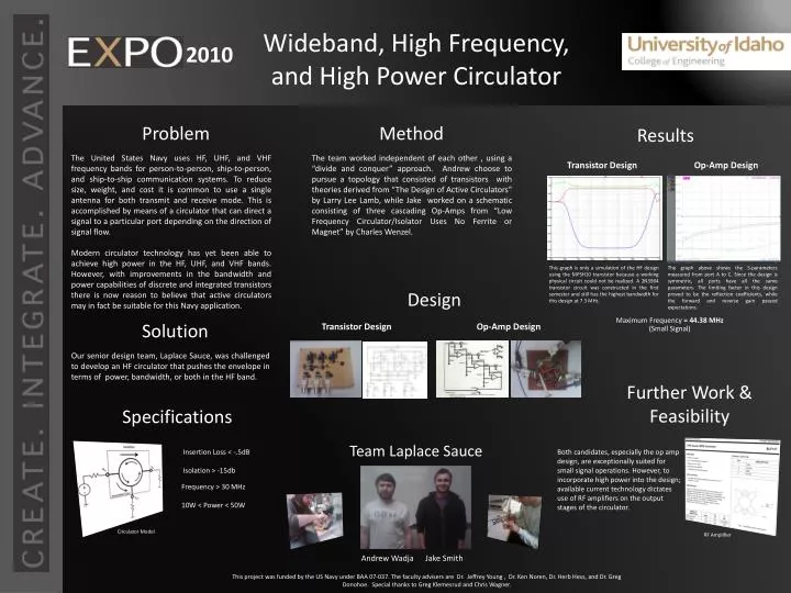
Wideband, High Frequency, and High Power Circulator. Problem. Method. Results.

E N D
Wideband, High Frequency, and High Power Circulator Problem Method Results The United States Navy uses HF, UHF, and VHF frequency bands for person-to-person, ship-to-person, and ship-to-ship communication systems. To reduce size, weight, and cost it is common to use a single antenna for both transmit and receive mode. This is accomplished by means of a circulator that can direct a signal to a particular port depending on the direction of signal flow. Modern circulator technology has yet been able to achieve high power in the HF, UHF, and VHF bands. However, with improvements in the bandwidth and power capabilities of discrete and integrated transistors there is now reason to believe that active circulators may in fact be suitable for this Navy application. The team worked independent of each other , using a “divide and conquer” approach. Andrew choose to pursue a topology that consisted of transistors with theories derived from “The Design of Active Circulators” by Larry Lee Lamb, while Jake worked on a schematic consisting of three cascading Op-Amps from “Low Frequency Circulator/Isolator Uses No Ferrite or Magnet” by Charles Wenzel. Transistor Design Op-Amp Design 2010 This graph is only a simulation of the HF design using the MPSH10 transistor because a working physical circuit could not be realized. A 2N3904 transistor circuit was constructed in the first semester and still has the highest bandwidth for this design at 7.3 MHz. The graph above shows the S-parameters measured from port A to C. Since the design is symmetric, all ports have all the same parameters. The limiting factor in this design proved to be the reflection coefficients, while the forward and reverse gain passed expectations. Design Maximum Frequency = 44.38 MHz Solution Transistor Design Op-Amp Design (Small Signal) Our senior design team, Laplace Sauce, was challenged to develop an HF circulator that pushes the envelope in terms of power, bandwidth, or both in the HF band. THS3061 THS Further Work & Feasibility Specifications Team Laplace Sauce Insertion Loss < -.5dB Isolation > -15db Both candidates, especially the op amp design, are exceptionally suited for small signal operations. However, to incorporate high power into the design; available current technology dictates use of RF amplifiers on the output stages of the circulator. Frequency > 30 MHz 10W < Power < 50W Circulator Model RF Amplifier Andrew Wadja Jake Smith This project was funded by the US Navy under BAA 07-037. The faculty advisers are Dr. Jeffrey Young , Dr. Ken Noren, Dr. Herb Hess, and Dr. Greg Donohoe. Special thanks to Greg Klemesrud and Chris Wagner.