Download
1 / 48
540 likes | 1.11k Vues
Mechanics of Materials Lab. Yielding and Failure Criteria Plasticity Fracture Fatigue Jiangyu Li University of Washington. Failure Criteria. Materials have flaw or crack in them: Linear Elastic Fracture Mechanics (LEFM)

E N D
Mechanics of Materials Lab Yielding and Failure Criteria Plasticity Fracture Fatigue Jiangyu Li University of Washington Jiangyu Li, University of Washington
Failure Criteria • Materials have flaw or crack in them: • Linear Elastic Fracture Mechanics (LEFM) • Stress intensity factor (K) describes the severity of the existing crack condition • If K exceeds the Critical stress intensity (Kc), then failure will occur • Materials Assumed to be perfect: • Brittle Materials • Max Normal Stress • Ductile Materials • Max Shear Stress • Octahedral Shear Stress Jiangyu Li, University of Washington
Maximum Normal Stress Fracture Criterion Jiangyu Li, University of Washington
Octahedral Shear Stress Criterion Jiangyu Li, University of Washington
Safety Factor and Load Factor • 7. 32 A circular bar must support a axial loading of 200 kN and a torque of 1.5 kN.m. Its yield strength is 260 MPa. • What diameter is needed if load factors YP=1.6 and YT=2.5 are required. Jiangyu Li, University of Washington
Stress Strain Curve Bauschinger Effect Jiangyu Li, University of Washington
Elastic-Perfect Plastic and Linear Hardening Jiangyu Li, University of Washington
Power Hardening and Ramberg-Osgood Relation Jiangyu Li, University of Washington
Secant Modulus Jiangyu Li, University of Washington
Stress-Strain Curve Jiangyu Li, University of Washington
Displacement Mode Sliding mode Opening mode Tearing mode Jiangyu Li, University of Washington
Stress Concentration Jiangyu Li, University of Washington
Stress Intensity Factor: Tension Jiangyu Li, University of Washington
Stress Intensity Factor: Bending Jiangyu Li, University of Washington
Stress Intensity Factor: Circumferential Crack - Jiangyu Li, University of Washington
Stress Intensity Factor Jiangyu Li, University of Washington
Superposition Jiangyu Li, University of Washington
Brittle vs. Ductile Behavior Jiangyu Li, University of Washington
Plastic Zone Jiangyu Li, University of Washington
Limitation of LEFM Jiangyu Li, University of Washington
Effect of Thickness Jiangyu Li, University of Washington
Correlation with Strength Jiangyu Li, University of Washington
Energy Release Rate Jiangyu Li, University of Washington
Strain Energy Increasing the strain rate increase strength, but decrease ductility Modulus of toughness & modulus of resilience Jiangyu Li, University of Washington
Charpy V-notch & Izod tests most common Energy calculated by pendulum height difference Charpy – metals, Izod - plastics Impact Test Jiangyu Li, University of Washington
Toughness is generally proportional to ductility Also dependent on strength, but not so strongly Brittle Fractures Lower energy Generally smooth in appearance Ductile Fracture Higher energy Rougher appearance on interior with 45° shear lips Trend in Impact Behavior Jiangyu Li, University of Washington
Effect of Temperature Decrease temperature increase strength, but decrease ductility Jiangyu Li, University of Washington
Ductile-Brittle Transition Jiangyu Li, University of Washington
Static Failure • Load is applied gradually • Stress is applied only once • Visible warning before failure Jiangyu Li, University of Washington
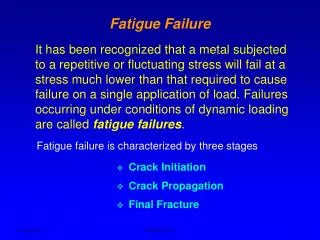
Cyclic Load and Fatigue Failure • Stress varies or fluctuates, and is repeated many times • Structure members fail under the repeated stresses • Actual maximum stress is well below the ultimate strength of material, often even below yield strength • Fatigue failure gives no visible warning, unlike static failure. It is sudden and catastrophic! Jiangyu Li, University of Washington
Characteristics • Primary design criterion in rotating parts. • Fatigue as a name for the phenomenon based on the notion of a material becoming “tired”, i.e. failing at less than its nominal strength. • Cyclical strain (stress) leads to fatigue failure. • Occurs in metals and polymers but rarely in ceramics. • Also an issue for “static” parts, e.g. bridges. • Cyclic loading stress limit<static stress capability. Jiangyu Li, University of Washington
Characteristics • Most applications of structural materials involve cyclic loading; any net tensile stress leads to fatigue. • Fatigue failure surfaces have three characteristic features: • A (near-)surface defect as the origin of the crack • Striations corresponding to slow, intermittent crack growth • Dull, fibrous brittle fracture surface (rapid growth). • Life of structural components generally limited by cyclic loading, not static strength. • Most environmental factors shorten life. Jiangyu Li, University of Washington
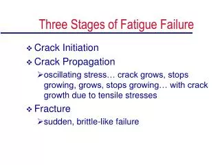
Fatigue Failure Feature • Flat facture surface, normal to stress axis, no necking • Stage one: initiation of microcracks • Stage two: progress from microcracks to macrocracks, forming parallel plateau-like facture feature (beach marks) separated by longitudinal ridge • Stage three: final cycle, sudden, fast fracture. Bolt, unidirectional bending Jiangyu Li, University of Washington
Fatigue-Life Method • Stress-life method • Facture mechanics method Jiangyu Li, University of Washington
Alternating Stress a = (max-min)/2 m = (max+min)/2 Jiangyu Li, University of Washington
S-N Diagram sa The greater the number ofcycles in the loading history,the smaller the stress thatthe material can withstandwithout failure. smean 3 > smean 2 > smean 1 smean 1 smean 2 smean 3 log Nf Note the presence of afatigue limit in manysteels and its absencein aluminum alloys. Jiangyu Li, University of Washington
S-N Diagram Endurance limit Jiangyu Li, University of Washington
Safety Factor Jiangyu Li, University of Washington
Facture Mechanics Method of Fatigue Jiangyu Li, University of Washington
Crack Growth > > Jiangyu Li, University of Washington
Fatigue Life Jiangyu Li, University of Washington
Crack Growth Rate Jiangyu Li, University of Washington
Fatigue Failure Criteria Jiangyu Li, University of Washington
Effect of Mean Stress Jiangyu Li, University of Washington
Fatigue Failure Criteria Multiply the stress By safety factor n Jiangyu Li, University of Washington
Example: Gerber Line AISI 1050 cold-drawn bar, withstand a fluctuating axial load varying from 0 to16 kip. Kf=1.85; Find Sa and Sm and the safety factor using Gerber relation Sut=100kpsi; Sy=84kpsi; Se’=0.504Sut kpsi Table 7-10 2 Change over 1 3 Jiangyu Li, University of Washington
Safety Factor with Mean Stress Jiangyu Li, University of Washington