Download

1 / 35
920 likes | 2.44k Vues
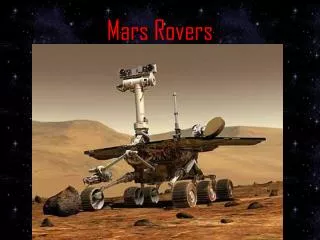
Mars Rovers. Definition and Motivation. A Mars rover is an automated motor vehicle which propels itself across the surface of the planet Mars after landing, it’s a NASA project specified to do a number of missions. The four goals of NASA's long-term Mars Exploration Program are:

E N D
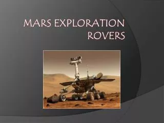
Definition and Motivation • A Mars rover is an automated motor vehicle which propels itself across the surface of the planet Mars after landing, it’s a NASA project specified to do a number of missions. • The four goals of NASA's long-term Mars Exploration Program are: • Determine whether life ever arose on Mars. • Characterize the climate of Mars. • Characterize the geology of Mars. • Prepare for human exploration.
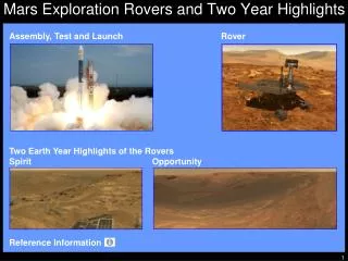
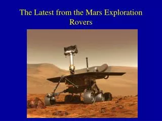
Key Facts • Missions to Mars started in early 1960s. • No human has ever stepped on Mars yet. Such trip would be a one way trip. The plan is to send a human in the next decade. • When the Curiosity rover touches the surface of Mars in August 2012, it will be the fourth rover to make tracks across the Red Planet in fifteen years after Sojourner 1997, and the rover twin Spirit and Opportunity 2003. • Average distance between Earth and Mars is 255 million km, it reached 56 million in 2003, and the farthest it can reach is 400 million km. The Mars day is 24 hours and 40 minutes. The cruise from earth to mars takes about 10 months. • MERs (Mars Exploration Rovers) Spirit & Opportunity were launched in 2003, each was on a different part of the plant as to enable the NASA team on Earth to work 24/7, or actually 24:40/7.
Curiosity is a rover that was supposed to be launched in 2009. It was launched on the 26th of November, 2011 with a total cost of 2.5 billion. The name Curiosity was chosen through a naming contest. • The rover weighs almost 862kg. Adding to it the weight of the spacecraft it rides in, and its landing system all together weigh 3400kg. Curiosity is twice the weight of Spirit and Opportunity together. • The testing was designed to put the rover through operational sequences in environmental conditions similar to what it will experience on the surface of Mars. The testing temperature approaches -130 C. Testing is done inside a lab and outside.
Specifications and Construction • Dimensions: The rover Curiosity is 3.0 m in length. • Speed: Maximum speed is estimated to be 2.5 cm/s, however, average speeds will likely be 0.8 cm/s based on variables including power levels, terrain difficulty, slippage, and visibility. It is expected to traverse a minimum of 19 km in its two-year mission. • Processor:There are two identical on-board rover processors.
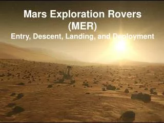
Communications:Curiosity has two means of communication: an X-bandtransmitter and receiver that can communicate directly with Earth, and a UHF band for communicating with Mars orbiters. • Communication with orbiters is expected to be the main contributor to data return to Earth, since the orbiters have both more power and larger antennas than the rover. Data includes photos, system-status information, etc. Also, the communication system enables scientists on earth to send data to the rovers such as commands and software updates to the rover. • At landing time, 13 minutes, 46 seconds will be required for signals to travel between Earth and Mars. Collected data need to be sent back to Earth. • There is a 20-minute round-trip delay because of the far distance between Earth and Mars. The rover transmits at only 12 kilobits per second. The direct link to earth is only available for about three hours per day because of the alignment of the planets and the power requirements of the radio.
Mobility systems:Curiosity is equipped with 6 wheels in a rocker-bogie suspensionsystem. Curiosity's wheels are significantly larger than those used on previous rovers. • Cameras: There are different types of cameras embedded on the rover that has different usages. Some are for taking photos of the landscape, other are specified as a sensing instruments, another acquire microscopic images of rock and soil. • Robot Arm: The Robot Arm is responsible of digging inside the rocks and soil of Mars, taking samples and pictures, and putting the samples in the right place on the rover so as to be able to send their pictures back to earth.
Energy System • Spirit and Opportunity (MERs) relies completely on the solar system. This made night missions impossible and day missions constricted by power. • Curiosityis powered by a radioisotope thermoelectric generator (RTG). Radioisotope power systems (RPSs) are generators that produce electricity from the natural radioactive decay of plutonium-238, which has the lowest shielding requirements and the longest half-life. • Heat given off by the natural decay of this isotope is converted into electricity by the Seebeck effect, providing constant power during all seasons and through the day and night, and waste heat can be used via pipes to warm systems since the rover will work in temperatures varying from -127 C to +30 C. Curiosity contains 4.8 kg of plutonium-238 dioxide.
Robot Arm • A robotic arm is a mechanical arm, with similar functions to a human arm. The links of such a manipulator are connected by joints allowing either rotational motion or translational (linear) displacement. • The robotic arm is designed to resemble the human arm that is able to grip, pick and place various objects. • A nearly six-foot-long, five-jointed arm for the Mars Science Laboratory is the most sophisticated robotic instrument positioning system yet designed for a space science mission.
The arm is a 5 joint robotic manipulator consisting of:1. Shoulder, elbow, wrist.2. An axis at the base.3. Fingers. • The whole robotic arm along with the rotating base is placed on a rover which exhibits forward, backward, left and right movements. • The robot arm has four fingers: • Microscope. • Two fingers are spectrometer to tell us in details what the rocks are made of, it is responsible for elemental and iron-mineral identification. • The RAT: the Rock Abrasion Tool which can grind into Mars rocks. The RAT uses a diamond-tipped robotic grinding tool to scrape away this weathered exterior, revealing a fresh surface.
Base motor is mounted vertically on a horizontal plane. Shoulder, elbow, tool pitch motors are mounted horizontally relative to the base. The tool roll and grip motors are mounted at the wrist joint.
Defining Parameters 1. Position and Orientation • Once a coordinate system is established, we can locate any point in the universe with a 3x1 position vector. The reference of the position vector is the coordinate system of the robot arm base. • Two axis are required to reach any position in a plane; three axis are required to reach any position in space. To fully control the orientation of the end of the arm (i.e. the wrist) three more axis are required.
It is necessary not only to represent the position of a point in space, but also to describe the orientation of the arm in space.Assuming that the manipulator has a sufficient number of joints, the arm can be oriented arbitrarily while keeping the fingertips at the same position in space. In order to describe the orientation of the arm, a coordinate system is attached to the fingertips relative to the reference system.
2. Carrying capacity or payload: how much weight a robot can lift. 3. Speed: how fast the robot can position the end of its arm. 4. Acceleration: how quickly a link can accelerate. 5. Accuracy: how closely a robot can reach a commanded position. When the absolute position of the robot is measured and compared to the commanded position the error is a measure of accuracy. 6. Degrees of freedom 7. Working Space
Robot Arms Design • Degrees of Freedom (DOF)The degrees of freedom, or DOF, is the number of joints on the arm, a place where it can bend or rotate or translate. When building a robot arm you want the less number of degrees of freedom allowed for your application because each degree requires a motor, often an encoder, and exponentially complicated algorithms and cost. If the degrees of freedom are increased, the workspace becomes bigger.
The Workspace • There are only two motions a joint could make: translate and rotate. • Each joint(DOF) has its limitations. Not all joints can swivel 360 degrees. For example, no human joint can rotate more than about 200 degrees. • The robot workspace is all places that the end effecter(gripper, grinder, etc) can reach. The workspace is highly dependent on the robot configuration. • The workspace is dependent on: • DOF angle/translation limitations • Arm links’ lengths • The angle at which something must be picked up at, etc.
Fields of Study 1. Forward KinematicsForward kinematics is the method for determining the position of the end effecter, given the joint angles and link lengths of the robot arm. • In the following example, the end effecter location with given joint angles and link lengths will be calculated. For simplicity, a three-degrees-of-freedom robot arm is considered. • Assume that the base is located at x=0 and y=0. The first step would be to locate x and y of all the joints. • Joint 1: x0=0; y0=L0.
For x1 and y1: cos(φ) = x1/L1 => x1 = L1*cos(φ) sin(φ) = y1/L1 => y1 = L1*sin(φ) • Joint 2: sin(θ) = x2/L2 => x2 = L2*sin(θ) cos(θ) =- y2/L2 => y2 = -L2*cos(θ) • End effecter location: x0 + x1 + x2, or 0 + L1*cos(φ) + L2*sin(θ) y0 + y1 + y2, or L0 + L1*sin(φ) + - L2*cos(θ) • The z component is dependent on alpha.
2. Inverse KinematicsInverse kinematics is the opposite of forward kinematics. This is when you have a desired end effecter position, but need to know the joint angles required to achieve it. • If the robot arm wants to go to a specific point in space, what angles should each joint go to? Derivation of the required equations is quite complex, but are given by:
What makes inverse kinematics so hard? Well, other than the fact that it involves non-linear simultaneous equations, there are other reasons too: • There is the very likely possibility of multiple, sometimes infinite, number of solutions (as shown below). • The difficulty for the arm to choose which is optimal, based on torques, previous arm position, gripping angle, etc. • There is the possibility of zero solutions. Maybe the location is outside the workspace.
3. Inverse Force Kinematics: After solving the inverse position kinematics problem for the current end effecter’s position, the inverse force kinematics then solves the following problem: "Given the final position of the end effecter, what is the corresponding joints’ forces and torques?“ • The following relations derives the torque required for maintaining the arm at a specific position. • The torque (T) is calculated using the following relation: • The force (F) acts at a length (L) from a pivot point. The force acting on an object (causing it to fall) is the acceleration due to gravity g =9.81 m/s2multiplied by its mass:
The force above is also considered the object's weight (W): • The torque required to hold a mass at a given distance from a pivot is therefore: • This can be found similarly by doing a torque balance about a point. Note that the length L is the perpendicular length from the pivot to the force. • Therefore, replacing F with m*g, we find the same equation above.
In order to estimate the torque required at each joint, we must choose the worst case scenario. • In the figure, a link of length L is rotated clockwise. Only the perpendicular component of length between the pivot and the force is taken into account. We observe that this distance decreases from L3 to L1 (L1 being zero). Since the equation for torque is length (or distance) multiplied by the force, the greatest value will be obtained using L3, since F does not change.
It can be safe to assume that the actuators in the arm will be subjected to the highest torque when the arm is stretched horizontally. Although the robot arm may never be designed to encounter this scenario, it should not fail under its own weight if stretched horizontally without a load. • The weight of the object (the "load") being held (A1 in the figure next slide), multiplied by the distance between its center of mass and the pivot gives the torque required at the pivot. • The equation takes into consideration that the links may have a significant weight (W1, W2..) and assumes its center of mass is located at roughly the center of its length. The torques caused by these different masses must be added:
You may note that the actuator weight A2 as shown in the figure below is not included when calculating the torque at that point. This is because the length between its center of mass and the pivot point is zero. Similarly, when calculating the torque required by the actuator A3, its own mass is not considered. The torque required at the second joint must be re-calculated with new lengths, as shown below:
What is Rocker Bogie? • The Rocker-Bogie system is the suspension arrangement used in the Mars rovers. This mechanism enables a six-wheeled vehicle to keep all six wheels in contact with a surface even when driving on severely uneven terrains. • Suspension is the term given to the system of springs, shock absorbers and linkages that connects a vehicle to its wheels. Suspension systems serve a dual purpose: contributing to the car's road holding/handling and braking. • Generally, exploration robots are driven on the rough surface which consists of different sized stones and soft sand. For this reason, car suspensions are not applicable for rovers.
Why Rocker Bogie in Rovers? • The most important factor when creating a suspension system for a rover is how to prevent it from suddenly and dramatically changing positions while cruising over rocky terrain. This might cause the flipping of the rover and it will mean the end of the mission. • The Rocker-Bogie design has no axles or springs, and allows the rover to climb over obstacles, such as rocks, that are up to twice the wheel's diameter in size while keeping all six wheels on the ground. However, the rocker bogie system in the rovers is very slow.
Number of Wheels • Four-wheel drive could have been used, but they do not climb obstacles very well, especially obstacles that are larger than the diameter of the wheels. • Six-wheel drive provides enough flexibility to climb over obstacles. Thus six-wheel system is used. • Eight-wheel drive would provide better climbing and vehicle control, however, more unnecessary wheels would mean more weight. To transfer 1 pound to mars you would need 1 extra million dollars, so weight is essential.
Each of the rover's six wheels has an independent motor. Each wheel also has cleats, providing grip for climbing in soft sand and scrambling over rocks. • Rover’s wheels have grown bigger starting with Sojourner and ending with Curiosity.
How the Rocker Bogie Works Front Wheel: • To go over an obstacle the front wheels are forced against the obstacle by the rear wheels. • The rotation of the front wheel then lifts the front of the vehicle up and over the obstacle. • The middle wheel is the pressed against the obstacle by the rear wheel and pulled against the obstacle by the front, until it is lifted up and over. • Finally, the rear wheel is pulled over the obstacle by the front two wheels. • During each wheel’s traversal of the obstacle, forward progress of the vehicle is slowed.
Rear Wheels: • When a wheel climbs up a step(say the rear wheel), the front and middle wheel are being pushed backwards and this would result in in wheel slippage. This problem can be improved by lowering the bogie pivot below the front wheel axis.
Done By: LoureenQussouss Esra’aSada Rami Abu Slayyeh Supervisor: Prof. Mohammad Zaki-Khadar