Download

1 / 55
1.23k likes | 2.36k Vues
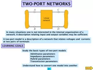
Chapter One. TWO-PORT NETWORK. TKT 419/3 Semester 2 Academic 2011/2012 Lecturer: Dr.Hilal Adnan (hilaladnan@unimap.edu.my). Coursework Contribution. COURSE IMPLEMENTATIONS Lecture : 3 hours per week for 14 weeks (Total = 42 hours).

E N D
Chapter One TWO-PORT NETWORK TKT 419/3 Semester 2 Academic 2011/2012 Lecturer: Dr.Hilal Adnan (hilaladnan@unimap.edu.my)
Coursework Contribution • COURSE IMPLEMENTATIONS • Lecture : 3 hours per week for 14 weeks (Total = 42 hours) • 2. Lecturer: Dr. Hilal A. Fadhil; and Prof. Dr. Syed A. Aljunid • Office: 1st Floor, House #8A, KKF 34, K.wei- Kuala Perlis • E-mail: hilaladnan@unimap.edu.my, Office tel#: 04-9852639. 3. COURSE OUTLINE: Chapter 1 : Two-Port Circuits Chapter 2 : Introduction to Laplace Transform Chapter 3:Frequency Response in AC Circuit Chapter 4: Fourier Series Chapter 5:Fourier Transform 4. TEXT BOOK: Electric Circuits, 9th Edition, by Nilsson/ Riedel
TWO-PORT NETWORK • Terminal equations • Two-port parameters • Relationships among two-port parameters • Analysis of terminated two-port circuit • Interconnected two-port circuits
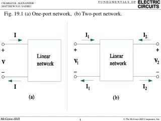
TERMINAL EQUATIONS s-domain two-port basic building block
Terminal equations relationships • 1st Relationship:
TWO PORT NETWORK: • Terminal equations • Two-port parameters • Relationships between parameters • Analysis of terminated two-port circuit • Interconnected two-port circuits
IMPEDANCE PARAMETERS • z parameters
b parameters a and b parameters are called transmission parameters
Example 1 • Find z parameter for the below circuit:
Solutions: • When port 2 open-circuit, I2=0 so,
TWO-PORT NETWORK • Terminal equations • Two-port parameters • Relationships between parameters • Analysis of terminated two-port circuit • Interconnected two-port circuits
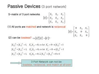
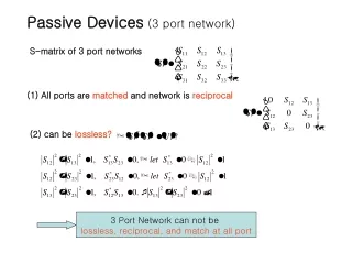
RECIPROCAL TWO-PORT CIRCUITS • If a two-port circuit is reciprocal, the following relationships exist among port parameters:
Symmetric of a reciprocal two-port circuits • Following relationships exist among port parameters:
Example of symmetric two-port circuits Symmetric tee
TWO-PORT NETWORK • Terminal equations • Two-port parameters • Relationships between parameters • Analysis of terminated two-port circuit • Interconnected two-port circuits
6 characteristics of terminated two-port circuit • Input impedance (Zin=V1/I1) or admittance (Yin=I1/V1) • Output current, I2 • Thevenin voltage and impedance (ZTh, VTh) with respect to port 2 • Current gain I2/I1 • Voltage gain V2/V1 • Voltage gain V2/Vg
6 characteristics in term of z parameters • 4 parameter equations that describe the circuit: …1 …2 …3 …4
1st characteristic (input impedance) In Eq(2) we replace V2 with –I2ZL and solve for I2 …..(5) Then substitute this Eq into eq(1), Zin=V1/I1
2nd characteristic (output current, I2) We solve Eq.(1) for I1 after replacing V1 with the right-hand side of Eq.(3) the result is : Then using Eq(5)
3rd characteristic (Thevenin voltage @ impedance) But V1=Vg-I1Zg , and then I1= Vg/(Zg+Z11)
Impedance Thevenin WHEN Vg is replacing by a short circuit (Vg=0), Eq(3) reduces to: V1=-I1 Zg Substituting the above eq into Eq(1) gives: ……(6) Now use Eq(6) to replace Eq(2) with the result that:
4th characteristic (current gain) From equation (5), the current gain is given by:
5th characteristic (voltage gain V2/V1) By replacing I2 in Eq.(2) with its value from Eq.(4); thus: …..7 …..8
We now replace I1 in Eq.(7) with Eq.(8) and solve the resulting expression for V2/V1:
6th characteristic (voltage gain V2/Vg) To derive the voltage ratio V2/Vg, we first combine Eqs(1) (3)(4) to find I1 as a function of V2 and Vg : ….(9) We now use Eq.(9) and Eq(4) in conjunction with Eq.(2) to derive an expression involving only V2 and Vg; that is:
Finally, we can manipulate to get the desired voltage ratio:
TWO-PORT NETWORK • Terminal equations • Two-port parameters • Relationships between parameters • Analysis of terminated two-port circuit • Interconnected two-port circuits