Download
1 / 25
270 likes | 774 Vues
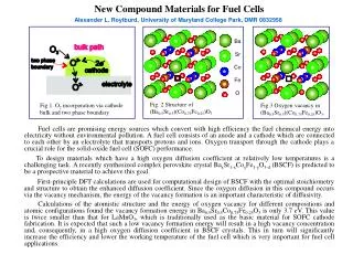
Chapter 7 Materials for Solid-Oxide Fuel Cells (SOFCs). Fuel Cell Background. In principle, fuel cells can be considered as batteries that convert chemical energy to electricity without combustion, but instead through electrochemical reactions.

E N D
Fuel Cell Background In principle, fuel cells can be considered as batteries that convert chemical energy to electricity without combustion, but instead through electrochemical reactions. The difference between fuel cells and conventional batteries is that fuel cells can run continuously as long as fuels are available for electrochemical reactions, whereas a battery needs to be recharged periodically. The concept of fuel cells was conceived by Sir William Robert Grove, known as the father of the fuel cell, who develop a ”gas voltaic battery” in 1839, later named the Grove cell. Accelerated research and engineering for fuel cell development started in the 1960s due to the unique needs for the long-endurance manned space exploration missions. For space applications, in addition to less toxcity, fuel cells have the advantage over traditional batteries, as they offer significantly higher energy density (energy per equivalent unit of weight) than conventional and advanced batteries.
Fuel cells are classified primarily according to the nature of the eletrolyte. Moreover, the nature of the eletrolyte governs the choices of the electrodes and the operation temperature. Shown in Table 10.1 are the fuel cell technologies currently under development. Technologies attracting attention toward development and commercialization include direct methanol (DMFC), polymer electrolyte membrane (PEMFC), solid-acid (SAFC), phosphoric acid (PAFC), alkaline (AFC), molten carbonate (MCFC), and solid-oxide (SOFC) fuel cells. This chapter is aimed at ten solid-oxide fuel cells (SOFCs) and related eletrolytes used for the fabrication of cells.
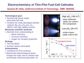
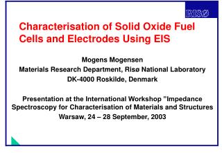
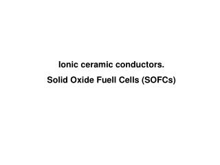
Cross section of the three ceramic layers of an SOFC. From left to right: porous cathode, dense electrolyte, porous anode
The Electrolyte for SOFCs The mobile species within a fuel cell are ions, which necessitate the electrolyte being an ionic conductor and electronic insulator. If the oxygen ions are the only charge carriers, the electron motive force (EMF) of the cell is determined from the chemical potential of oxygen (i.e., oxygen activity), which is expressed by the Nernst equation as where Γ is the ionic transference number (ionic conductivity/total conductivity), Γ is the cell operation temperature, F is the Faraday constant, (pO2)a is the oxygen partial pressure (fugacity/activity) at the cathode side, and (pO2)b is similarly the oxygen partial pressure (fugacity/activity) at the cathode side. In the case of an open circuit (without external current flow), the EMF of the cell corresponds to the open-circuit voltage (OCV).
Requirements Long-term successful operation of SOFCs requires that the electrolyte possess adequate chemical and structural stability over a wide renge of oxygen partial pressures, form air or oxygen to humidfied hydrogen or hydrocarbons. The requirements for the electrolyte used in the intermediate-temperature SOFCs (IT SOFCs) include: Conductivity: The materials must have an ionic transference number close to unity; i.e., the electronic conductivity in the electrolyte must be sufficiently low in order to minimize internal shorting and provide high energy conversion efficiency. The electrolyte materials should also possess high oxygen ion conductivity to minimize the ohmic losses in the cell.
Density: In order to minimize molecular transport of gases across the electrolyte membrane and prevent combustion (to produce maximum power density), the electrolyte must remain gas tight during the life of the cell. This indicates that when we consider the SOFC electrolyte, the main challenge has to be related to the processing of dense, thin electrolyte layers using either the anode or cathode as the supporting structure. Stability: The operation of SOFCs requires the cathode and the anode to be porous for gas transport; therefore, the electrolyte is exposed to both the air and the fuel at elevated temperature. The electrolyte must remain chemically phase stable in these environments, along with thermal and mechanical stability during thermal cycling. This requires matching of the thermal expansion coefficients of adjoining layers. Chemical interactions and formation of interfacial compounds between adjoining components must also be minimized or prevented to mitigate increase in cell resistance and polarization losses. It should be kept in mind that the SOFCs, currently designed for stationary applications, have a target life of 40,000 h, and hence the long-term chemical and structural stability of the electrolyte plays a crucial role.
Materials The most commonly used electrolyte materials under development and deployment in SOFCs are the oxides with low-valence element substitutions, sometimes named acceptor dopant, which create oxygen vacancies through charge compensation. It is straightforward to design the oxygen ion conductors by increasing the oxygen vacancy concentration. This, however, may not be valid in many cases, as other factors, such as vacany ordering charge mobility, and compatibility with other cell components, must also be taken into consideration. As a result, the most commonly utilized electrolyte materials that can satisfy these requirements are Y-stabilized ZrO2 (YSZ), with acceptor-substituted CeO2 and (La,Sr)(Mg,Ga)O3. Other interesting electrolyte materials include pseudo-perovskite structures, Bi4V2O11 (MIMEVOX) and La2Mo2O2; pyrochlore structures, (Gd,Ca)2Ti2O7 ; and apatites, La10-XSr6O26.
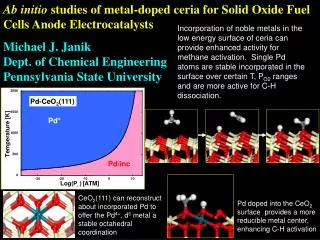
Fluorites: ZRO2, CEO2, and Bi2O3 The fluorite class of oxides is most studied as solid-oxide electrolyte materials because of their chemical and structural stability. The fluorite lattice structure is basically face center cubic (FCC; space group, Fm3m) with a general formula of MO2, in which M typically is Zr or Ce, as in ZrO2 or CeO2. There are four MO2 formulas in unit cell, in which cations are in cubic closest packing with oxygen ions in all tetrahedral holes. The CeO2 lattice is known to possess a large open-volume fraction (>35 %) and, as a result, is capable of tolerating oxygen nonstoichiometry and forming solid solution with various low-valence elements. This gives the materials scientist an opportunity to alter the properties of a given base oxide by substituting different cations or varying oxygen content.
Perovskites LaGaO3 The perovskite structure is basically cubic with the genertral formula of ABO3, in whick A, the large cation site, is an alkaline earth, or rare earth ion, and B, the small cation site, is a transition metal cation. The large cations are in 12-fold coordination with oxygen, while the small cations fit into octahedral positions. The occupancy of these sites by different cations is determined primarily by ionic radius rather than the valence. The opens the door for the materials scientists to substitute selectively for either the A or B ion by introducing isovalent or aliovalent cations. An oxygen ion conductor can be tailored because of the geometrical and chemical flexibility of the perovskite structure. This is borne out by(La,Sr)(Mg,Ga)O3 (LSMG), which has attracted great attention since its discovery.
There exist, however, two drawbacks for LSMG electrolytes: (1) the uncertainty in the cost of Ga sources and (2) the chemical and mechanical stability of LSMG. It is apparent that ordering occurs (sometimes at specific temperatures) that significantly decreases the oxygen ionic conductivity because of lower defect mobility and reduced effective vacancy concentration. Stevenson et al. studied the role of microstructure and nonstoichiometry on ionic conductivity of LSMG. The electrical conductivity of sintered LSGM tends to decrease with increasing A/B cation nonstoichiometry. The flexural strength of LSGM with an A/B cation ratio of 1.00 was also measured and found to be closer to 150 MPa at room temperature, and the strength decreased to 100 MPa at higher temperatures (600 to 1,000 ℃). The fracture toughness, as measured by notched beam analysis, was closer to 2.0 to 2.2 MPa at room temperature, with similar reduction to 1.0 MPa at 1,000 ℃.
Other phases There are many other solid-state oxide ion conductors, primarily derived from either fluoite or perovskite structures. The perovskite-related oxide ion conductors include (1) Ln(Al,In,Sc,Y)O3-based materials, (2) the doped and undoped brownmillerite Ba2In2O5, and (3) La2Mo2O9. The transference number of doped La2Mo2O9 can be higher than 0.99 in an oxidant environment. The drawbacks of La2Mo2O9-based materials are instability in reducing conditions, a relatively large thermal expansion coefficient (>16 ppm/K for La1.7Bi0.3Mo2O9), and the order of the anion sublattice. Doped LaAlO3 has reasonable ionic conductivity (~0.006 S/cm at 800 ℃) and excellent thermal expansion coefficient (TEC) match with other components (~11 ppm/K); however, it is rather challenging to sinter LaAlO3-based oxides and to prevent the formation of highly insulating grain boundary phases (Al2O3).
Corrosion and Protection of Metallic Interconnects Among the various types of fuel cells, solid-oxide fuel cells (SOFCs) operate at high temperature (typically 650 to 1,000 ℃) and have advantages in term of high conversion efficiency and the flexibility of using hydrocarbon fuels, in addition to hydrogen. The high-temperature operation, however, can lead to increased mass transport and interactions between the surrounding environment and components that are required to be stable during a lifetime of thousands of hours and up to hundreds of thermal cycles. For stacks with relatively low operating temperatures (< 800 ℃), the interconnects that are used to electrically connect a number of cell in series are typically made from cost-effective metals or alloys. The metallic interconnects must demonstrate excellent stability in a very challenging environment during SOFC operation.
Until recently, the leading candidate material for the interconnect was doped lanthanum chromite, LaXSr1-XCrO3, a ceramic that could easily withstand traditional 900 to 1,000 ℃ operating temperature. The recent trend in developing lower-temperature (650 to 800 ℃), more cost-effective cells that utilize anode-supported, thin electrolytes or new electrolytes with improved conductivity makes it feasible for lanthanum chromite to be supplanted by cost-effective metals or alloys as the interconnect materials. The metals are typically those alloys that contain “active” constituents, mainly Cr, Al, or Si, which are preferentially oxidized at the surface to form an oxide scale that minimizes further environmental attack during high-temperature exposure.
Surface Modification for Improved Stability For satisfactory long-term stability against oxidation and corrosion, metallic interconnects are often coated with a protection layer that helps minimize electrical contact resistance and mitigate or prevent potential cell degradation due to chromia scale evaporation. Functionally, the protection layer is intended first to serve as a mass barrier to both chromium cation outward and oxygen inward transport (via solid-stare diffusion if the barrier contains no open porosity).
References • Materials for the Hydrogen Economy, Jones, R. H. and Thomas, G. J., ed., CRC Press, Boca Raton, 2008. • http://en.wikipedia.org/wiki/Solid_oxide_fuel_cell