Download
1 / 19
190 likes | 311 Vues
Virtual Rumble Strip MDR. Advisor: Prof. Kelly Members: Matt Auby Steve Leblanc Joachim Weyl Mariah Winkler. Background and Motivation. Single Vehicle Roadway Departure (SVRD) Account for 20% of all crashes, but nearly 50% of all fatal crashes

E N D
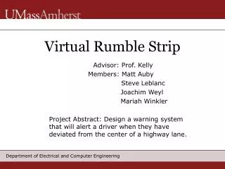
Virtual Rumble Strip MDR Advisor: Prof. Kelly Members: Matt Auby Steve Leblanc Joachim Weyl Mariah Winkler
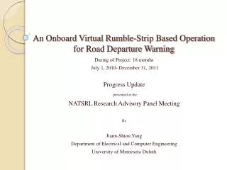
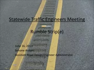
Background and Motivation • Single Vehicle Roadway Departure (SVRD) • Account for 20% of all crashes, but nearly 50% of all fatal crashes • Rumble strips • Help prevent SVRD accidents in the outer lanes • What about the middle lanes? • No system in place to warn people drifting between lanes on a fast highway.
Approved MDR Specifications • Settled on a Sensor system. • Optical vs. Microwave • Settled on a Design for the Sensor Array. • Should it be two rows of sensors or should it be a V formation, how many sensors, etc. • Show that the Sensor Array gives usable results. • Show that the sensor array is providing the necessary data to give suitable feedback to the driver.
Alternative Sensors • Investigated Microwave Sensors • Easy measurements of distances ahead to echo objects. • Similar system designed in 1997 called the FSS Highway Stripe. • Beyond the Scope of a 1 yr. SDP • Keep original focus of an inexpensive alternative
Approved MDR Specifications • Settled on a Sensor system. • Optical vs. Microwave • Settled on a Design for the Sensor Array. • Should it be two rows of sensors or should it be a V formation, how many sensors, etc. • Show that the Sensor Array gives usable results. • Show that the sensor array is providing the necessary data to give suitable feedback to the driver.
Sensor Hardware • 4 different sensors tested • Best results came from the 701AL because it uses a Darlington configuration • The 701AL is smaller then some of the other sensors tested • 14 different colored strips tested on road surface • All bright colors appear to reflect very well while all dark colors appear to work poorly • This will help sense the road using the lines already laid down
Approved MDR Specifications • Settled on a Sensor system. • Optical vs. Microwave • Settled on a Design for the Sensor Array. • Should it be two rows of sensors or should it be a V formation, how many sensors, etc. • Show that the Sensor Array gives usable results. • Show that the sensor array is providing the necessary data to give suitable feedback to the driver.
Car Mounted Array System • Array mounted under of the car • Single line array • 13 Sensors will be mounted under the car. • 3 Middle sensors • 10 Warning sensors
Approved MDR Specifications • Settled on a Sensor system. • Optical vs. Microwave • Settled on a Design for the Sensor Array. • Should it be two rows of sensors or should it be a V formation, how many sensors, etc. • Show that the Sensor Array gives usable results. • Show that the sensor array is providing the necessary data to give suitable feedback to the driver.
Human Factors • Visual Component • First Line of Defense • Motion Enhanced Warning Signal (MEWS) • Audio Component • Second Line of Defense • A graded signal presented in Stereo • Two separate tones
Warning System • Prototype Drawing of the Warning System
Behavioral Changes • Lane Deviation Distribution • May compress because drivers get it know how far they can deviate without being warned • Drowsiness • Driver may become less attentive to his/her surroundings
Looking Ahead • Sensor Array • DSP, Gain Block and Noise Filtering • Attach Prototype to RC Car • Warning System • Build the Prototype • Try to implement ways to deal with Behavioral Changes • Questions or Comments
Approved MDR Specifications • Settled on a Sensor system. • Optical vs. Microwave • Settled on a Design for the Sensor Array. • Should it be two rows of sensors or should it be a V formation, how many sensors, etc. • Show that the Sensor Array gives usable results. • Show that the sensor array is providing the necessary data to give suitable feedback to the driver.