Download
1 / 8
80 likes | 81 Vues
Essential protection principles<br><br>This technical article covers 4 fundamental principles of protection:<br><br><br>Fundamentals of protection against overcurrents, distances, and distances (photo credit: Power Research & Development Consultants Pvt. Ltd)<br><br>1. Principle of overcurrent protection<br><br>2. Principle of directional overcurrent protection<br><br>3. Principle of distance protection<br><br>4. Differential protection principle

E N D
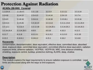
Fundamentals of protection against overcurrents, distances, and differences Essential protection principles This technical article covers 4 fundamental principles of protection: Fundamentals of protection against overcurrents, distances, and distances (photo credit: Power Research & Development Consultants Pvt. Ltd) 1.Principle of overcurrent protection 2.Principle of directional overcurrent protection 3.Principle of distance protection 4.Differential protection principle 1.For transmission line 2.For transformer 3.For busbars To simplify the explanation of key ideas, we consider three-phase bolted faults. 1. Over-current protection This diagram is based on the intuition that, typically short circuit faults, lead to currents much greater than the load current. We can call them overcurrents. The overcurrent relay and the fuse protection use the following principle: when the current exceeds a predetermined value, it indicates the presence of a fault (short circuit).
This protection scheme finds use in radial distribution systems with a single source. It is quite simple to implement. The fault current is supplied from only one end of the feeder. For this system, we can observe that: To relay R 1, the two downstream faults F 1 and F 2 are visible, ie. I F1 as well as I F2 go through CT of R 1. To relay R 2, fault F 1, an upstream fault is not seen, only F 2 is seen. Indeed, no component of I F1 passes through CT of R 2. Thus, selectivity is obtained naturally. The relay decision is based solely on the magnitude of the fault current. Such a protection system is said to be non- directional. 2. Directional overcurrent protection On the other hand, there may be situations where, for reasons of selectivity, phase angle information (still with respect to a reference phasor) may be necessary. Figure 2 shows such a case for a radial system with a source at both ends. Therefore, the fault is fed from both ends of the feeder. To interrupt the fault current relays at both ends of the charger is required. In this case, from the magnitude of the current seen by the relay R 2, it is not possible to distinguish whether the fault is in section AB or BC. Since faults in the AB section are outside his jurisdiction, he should not stumble.
To achieve selectivity, a directional overcurrent relay is required. It uses both current magnitude and phase angle for decision-making. It is commonly used in sub-transmission networks where ringing networks are used. 3. Distance protection Consider a simple radial system fed by a single source. Let us measure the Apparent Impedance (V / I) at the end of the shipment. For the unloaded system, I = 0, and the apparent impedance is seen by the relay is infinite. When the system is loaded, the apparent impedance is reduced to a finite value ( Z L + Z line ) where Z L is the load impedance and Z line is the line impedance. In the presence of a fault at a unit distance "m", the impedance is seen by the relay drops to an MZ line as shown in Figure 3 below. The basic principle of the distance relay is that the apparent impedance seen by the relay, defined as the ratio between the phase voltage and the line current of a transmission line ( Z app ), reduces considerably in the presence of a line fault. A distance relay compares this ratio with the positive sequence impedance (Z 1 ) of the transmission line. If the fraction Z app / Z 1 is less than unity, this indicates a fault. This report also indicates the distance of the fault from the relay. Because impedance is a complex number, distance protection is inherently directional. The first quadrant is the forward direction, i.e. the impedance of the transmission line to be protected is located in this quadrant.
However, if only the magnitude information is used, the result is a non- directional impedance relay. Figures 4 and 5 show a characteristic of an impedance relay and "mho relay" both belonging to this class. The impedance relay trips if the magnitude of the impedance is in the circular region. As the circle covers all quadrants, the result is a non- directional protection system. In contrast, the mho relay which mainly covers the first quadrant is directional in nature. Thus, the trigger law for the impedance relay can be written as follows: | Z app | = | V R | / | I R | <| Z together | then travel; otherwise, restrict. While the impedance relay has only one design parameter, Z together; The “mhorelay” has two design parameters Z n, λ. The tripping law for the mho relay is given by if: | Z app | <| Z n | cos (θ - λ) then travel; otherwise, restrict. As shown in Figure 5, θ is the angle of the transmission line. Based on the legacy of electromechanical relays λ is also called "torque angle". 4. Principle of differential protection
Differential protection is based on the fact that any failure of electrical equipment would cause current to enter it, being different from the current leaving it. Thus, by comparing the two currents either in amplitude or in phase, or both, we can determine a fault and issue a trip decision if the difference exceeds a predetermined value. 4.1 Differential protection for the transmission line Figure 6 shows a short transmission line in which the bypass load can be neglected. Then, in the absence of any fault, the sum of the phasor currents entering the device is zero, that is to say i S + I R = 0 Thus, we can say that the differential current without fault condition is zero. However, in the event of a fault in the line segment AB, we obtain: i S + I R = I F≠ 0 i.e. that the differential current in the presence of a fault is not zero. This principle of differential current control is known as a differentiated protection regime. In the case of the transmission line, the implementation of the differential protection requires a communication channel to transmit the current values to the other end. It can be used for short power supplies and a specific implementation is known as pilot wire protection. Differential protection
tends to be extremely precise. Its area is clearly delimited by the TCs which delimits the border. Differential protection can be used for highlighted lines (multi-terminal lines) where limit conditions are defined as follows: Under no error condition: i 1 + i 2 + i 3 = 0 Reproached on condition: I 1 + I 2 + I 3≠ 0 4.2 differential protection for transformer Differential protection for fault detection is an attractive option when the two ends of the device are physically close to each other. for example on a transformer, a generator, or a bus bar. Consider an ideal transformer with CT connections, as shown in Figure 8.
To illustrate the principle, consider that the rated primary winding current is 100A and the secondary winding is 1000A. Then, if we use 100: 5 and 1000: 5 CT on the primary and secondary winding, then, under normal (no-fault) operating conditions, the scaled CT currents will correspond in magnitudes. By carefully connecting the primary and secondary CTs to the points (polarity markings), a flowing current can be built up as indicated by a dotted line. No current will flow in the branch having an overcurrent current relay because it will result in a KCL violation. Now if an internal fault occurs in the device like inter-turn short etc. then the normal mmf equilibrium is upset i.e. N 1 I 1≠ And 2 I 2. Under these conditions, the CT secondary currents of the primary and secondary CTs will not match. The resulting differential current will flow through the excess current relay. If the overcurrent relay's plug-in setting is close to zero, it will immediately take and initiate the trip decision. In practice, the transformer is not ideal. Therefore, even if I 2 = 0, I 1≠ 0 it is the magnetizing current or (without load) current. Thus, a differential current always flows through the overcurrent relay. Therefore, the overcurrent relay pickup is adjusted above the no-load current value. Therefore, it is impossible to detect minor faults below the zero loads current value. This compromises the sensitivity. 4.3 differential protection for busbar
Ideally, differential protection is the solution for busbar protection. Figure 9 illustrates the basic idea. If the fault is external to the bus, we can see that the algebraic sum of the currents entering the bus is zero. I A + I B + I C + I d + I E = 0 Figure 9 - differential protection of the support bar On the other hand, if the fault is on the bus (internal fault) this sum is not equal to zero. I A + I B + I C + I d + I E = I F Thus, differential protection can be used to protect a bus. BurraqEngineering Solutions is the best training institute in Lahore which is providing practical training of Electrical Automation and Short Electrical Courses including PLC course, SOLAR SYSTEM Installation, and DESIGN COURSE, ETAP course, DIALUX course, Panel FABRICATION course, VFD course, ADVANCED control panel, SWITCHERGEAR design course, Building Electrical design course and all electrical diploma courses. Both online and physical classes available. We introduce a platform Lyskills from where you can get lifetime access to your desire courses at a very reasonable price.