Download
1 / 16
290 likes | 1.2k Vues
Optical Network Management Fault Management And Service Recovery. Prepared For: ITU-T Workshop On IP/Optical Chitose, Japan, 9-11 July 2002. Tobey Trygar ttrygar@telcordia.com +1 732 758-5399. Outline. Definition of Fault Management Scope of Fault Management

E N D
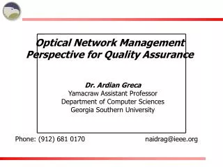
Optical Network ManagementFault Management And Service Recovery Prepared For: ITU-T Workshop On IP/Optical Chitose, Japan, 9-11 July 2002 Tobey Trygar ttrygar@telcordia.com +1 732 758-5399
Outline • Definition of Fault Management • Scope of Fault Management • Transmission Fault Event Classes • Generic Layer Networks • Optical Transport Network (OTN) Layers • OTN Supervision and Fault Management Processes • Key Aspects of Service Recovery
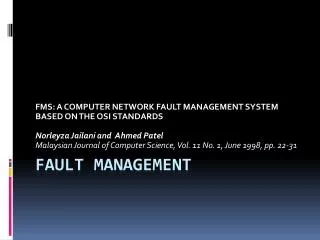
Fault Management • Fault Management is the process of • detecting, • isolating, and • correcting the abnormal operation of a telecommunications network and its environment. • M.3010 defines a management structure that contains five layers, namely the business management, the service management, the network management, the element management and the network element layer. • This presentation addresses the network element layer and the functions that are supported within optical network elements.
Trouble Event Taxonomy Trouble Events Fault Event Performance Event Alarmed Non-Alarmed Critical Major Minor Warning Defects Anomalies
Fault Management Scope • In general, Fault Management addresses the following five classes of trouble events: • Events related to the received Transmission signal content and structure • Events related to severe Quality of Service degradations • Events related to software Processing • Events related to network Equipment replaceable modules • Events related to theEnvironment in which the equipment resides • The remainder of the presentation will focus on transmission signal related events.
Fault Management Transmission Events • Continuity supervisionto detect loss of the transmission signal • Connectivity supervisionto detect misconnections • Signal quality supervision to detect signal degradation • Payload type supervision to detect inconsistencies between the transmitted signal and the expected received signal • Multiplex structure supervision to detect inconsistencies between the transmitted and expected received signal • Alignment supervision to detect framing problems • Protocol supervision to detect inconsistent or unexpected protocol exchanges
G.805 Network Classes • There are two broad classes of transport layer networks - Path Layer Networks and Transmission Media Layer Networks. • Path Layer Networks • Independent of the physical media which supports the communications signal, e.g., STM-1 electrical section or an STM-1 in an optical section, or via a microwave radio link. • Defined in terms of signal hierarchies, SDH, PDH, ATM VC-VP. • Transmission Media Layer Networks are divided into • Section Layer Networks which are related to the technology implementing the transmission system. They are based on the multiplexers, cross-connects, and regenerators. • Physical Media Layer Networks which contain the collection of interconnected media, e.g., twisted pairs, optical fibers, coaxial cables, waveguides etc., that carry the communication signals.
= Adaptation Function = Trail Termination Function = Subnetwork Connection G.805 View Of Layer Relationships - Bi-directional Transmission CP CP Link Connection Client Layer Network Trail AP AP Server Layer Network Subnetwork Connection Link Connection TCP TCP Network Connection AP = Access Point CP = Connection Point TCP = Termination Connection Point
Fault Management Processes (G.7710, G.874) Management Application Functions (M Series) Supervision And Management Processes Within An Adaptation Function Connection Point Management Points (MP) Supervision Processes (G.806, G.798) Data and Maintenance Signals Layer-Descriptor_Adaptation_Sink_Function Access Point
Layers Defined For The Optical Transport Network1 • Digital Optical Transport Network (OTN) Layers • Optical Channel Data Unit (ODU), Path and Tandem Connection • Optical Channel Transport Unit (OTU) • Original OTN Layers • Optical Channel (OCh) Layer, OCh Reduced (OChr) • Optical Multiplex Section (OMS) Layer • Optical Transmission Section (OTS) Layer • Optical Physical Section (OPS) Layer • Fault Management is concerned with received transmission signals as contrasted with transmitted signals. 1 See Recommendation G.872
Physical View Of A Linear OTN OTN Client Signal OTN Client Signal ODU ODU Termination ODU Termination OCh/OTU OCh/OTU OCh/OTU Termination OCh/OTU Termination OCh/OTU Termination OMS OMS OMS OMS Termination OMS Termination OMS Termination OMS Termination OTS OTS OTS OTS OTS OTS Termination OTS Termination OTS Termination OTS Termination OTS Termination OTS Termination Physical Layer Physical Layer Physical Layer Physical Layer Physical Layer Physical Layer ONE ONE ONE ONE ONE ONE ONE = Optical Network Element
Supervision Processes Information Flow Across A Management Point At A Given Atomic Function (Sink) Fault Management Processes Management Application Functions Alarm Severity Assignment Profile ARC information Unit Alarms UNA Failure Reportable Failure Network Element Fault cause Alarms REP PRS SEV ARC NEA cZZZ-value MP fZZZ-value fZZZ-value rZZZ-value Station Alarms fZZZ-severity STA rZZZ-severity fZZZ-value fZZZ-severity TEP fZZZ-arc Alarm Synchronization ASY rZZZ-value rZZZ-severity Query LOG Report TMN alarm event notifications TAN Current Problem List CPL Alarm Status AST Operational State OPS
Management Point ODUkPath_Trail-Termination_Sink Supervision Process Fault Management Process Open Connection Indication Trace Identifier Mismatch Signal Degrade Backward Defect Indications Server Signal Fail Locked Signal OTN Fault Indicators • G.798/G.874 specify 21 supervision processes for the OTN layers. • These 21 processes generate 69 fault cause indicators. • The fault cause indicators that an optical network element may generate depend on the number of trail termination and adaptation sink functions it contains.
Management Request or Qualified Problem Free or Timer Expired Management Management Management Management Management Management Request Request Request Request Request Request Timer Expired Management Request or Timer Expired Alarm Report Control NALM - QI ALM = Alarmed NALM = Not Alarmed TI = Timed Inhibit QI = Qualified Inhibit NR = Not Ready CD = Count Down do: Alarm Reporting Inhibited Modify Interval NALM- CD entry: reset timer (1) entry: reset timer (1) Qualified Qualified Problem Problem Raised Free Qualified Problem Free NALM-NR ALM NALM Management Request do: Alarm Reporting Inhibited do: Alarm Reporting Allowed Management Request Modify Interval NALM-TI entry: reset timer do: Alarm Reporting Inhibited
Key Aspects Of Service Recovery • For protected services, recovery may be accomplished via protection schemes if the failure event is not too extreme. • Re-routing, (restoration), can recover services again provided that the failure event is not too extreme. • Assuming that conventional methods succeed, the network may be vulnerable to future failure events. • To provide support for an Emergency Service per E.106, F.706 and Y.roec, special consideration must be given to the assignment of alarm severity levels. • Given the extensive capacity of the OTN, e.g., from 2.5 to 40 gigabits per second per channel, enhanced OTN services such as emergency service, are best provided via Service Level Agreements.
References • E.106, Description of an International Emergency Preference Scheme (IEPS) • F.706, (Draft), International Emergency Multimedia Service • G.709, Network Node Interface For The Optical Transport Network (OTN) • G.798, Characteristics of Optical Transport Network Hierarchy Equipment Functional Blocks • G.805, Generic Functional Architecture Of Transport Networks • G.806, Characteristics of Transport Equipment - Description Methodology and Generic Functionality • G.872, Architecture Of Optical Transport Networks • G.874, Management Aspects Of Optical Transport Network Elements • G.7710, Common Equipment Management Function Requirements • G.7712, Architecture And Specification Of Data Communication Network • M.3010, Principles For A Telecommunications Management Network • M.3013, Considerations For A Telecommunications Management Network • M.3100, Generic Network Information Model • Y.roec, (Draft), Framework(s) on Network Requirements and Capabilities to Support Emergency Communications Over Evolving Circuit Switched and Packet Switched Networks