ZigBee/IEEE 802.15.4 Overview
ZigBee/IEEE 802.15.4 Overview. Y. C. Tseng. New Trend of Wireless Technology. Most Wireless industry focus on increasing high data throughput A set of applications requiring simple wireless connectivity, relaxed throughput, very low power, short distance and inexpensiveness: Industrial

ZigBee/IEEE 802.15.4 Overview
E N D
Presentation Transcript
ZigBee/IEEE 802.15.4 Overview Y. C. Tseng
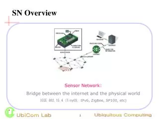
New Trend of Wireless Technology • Most Wireless industry focus on increasing high data throughput • A set of applications requiring simple wireless connectivity, relaxed throughput, very low power, short distance and inexpensiveness: • Industrial • Agricultural • Vehicular • Residential • Medical
What is ZigBee Alliance? • An organization with a mission to define reliable, cost effective, low-power, wirelessly networked, monitoring and control products based on an open global standard • The alliance provides interoperability, certification testing, and branding.
IEEE 802.15 Working Group Zigbee UWB
Wireless Markets TEXT GRAPHICS INTERNET HI-FI AUDIO STREAMING VIDEO DIGITAL VIDEO MULTI-CHANNEL VIDEO LAN 802.11b 802.11a/HL2 & 802.11g SHORT < RANGE > LONG Bluetooth 2 ZigBee PAN Bluetooth1 LOW < DATA RATE > HIGH
ZigBee/IEEE 802.15.4 Market Feature • Low power consumption • Low cost • Low offered message throughput • Supports large network orders (<= 65k nodes) • Low to no QoS guarantees • Flexible protocol design suitable for many applications
INDUSTRIAL & COMMERCIAL ZigBee Network Applications CONSUMER ELECTRONICS monitors sensors automation control TV VCR DVD/CD Remote control PC & PERIPHERALS PERSONAL HEALTH CARE monitors diagnostics sensors ZigBee LOW DATA-RATE RADIO DEVICES mouse keyboard joystick TOYS & GAMES HOME AUTOMATION security HVAC lighting closures consolesportables educational
Range Meters GSM GPRS EDGE 3G 2000 10,000 2003-4 2005 1,000 802.11b 802.11a/g ZigBee 100 Hiper LAN/2 Bluetooth 2.0 Bluetooth Bandwidth kbps WiMedia Bluetooth 1.5 10 10 100 1,000 10,000 100,000 Wireless Technologies
ZigBee/802.15.4 Architecture • ZigBee Alliance • 45+ companies: semiconductor mfrs, IP providers, OEMs, etc. • Defining upper layers of protocol stack: from network to application, including application profiles • First profiles published mid 2003 • IEEE 802.15.4 Working Group • Defining lower layers of protocol stack: MAC and PHY
How is ZigBee related to IEEE 802.15.4? • ZigBee takes full advantage of a powerful physical radio specified by IEEE 802.15.4 • ZigBee adds logical network, security and application software • ZigBee continues to work closely with the IEEE to ensure an integrated and complete solution for the market
ZigBee/802.15.4 Technology: General Characteristics • Data rates of 250 kbps , 20 kbps and 40kpbs. • Star or Peer-to-Peer operation. • Support for low latency devices. • CSMA-CA channel access. • Dynamic device addressing. • Fully handshaked protocol for transfer reliability. • Low power consumption. • 16 channels in the 2.4GHz ISM band, 10 channels in the 915MHz ISM band and one channel in the European 868MHz band. • Extremely low duty-cycle (<0.1%)
IEEE 802.15.4 Basics • 802.15.4 is a simple packet data protocol for lightweight wireless networks • Channel Access is via Carrier Sense Multiple Access with collision avoidance and optional time slotting • Message acknowledgement and an optional beacon structure • Multi-level security • Works well for • Long battery life, selectable latency for controllers, sensors, remote monitoring and portable electronics • Configured for maximum battery life, has the potential to last as long as the shelf life of most batteries
IEEE 802.15.4 Device Types • There are two different device types : • A full function device (FFD) • A reduced function device (RFD) • The FFD can operate in three modes serving • Device • Coordinator • PAN coordinator • The RFD can only operate in a mode serving: • Device
FFD vs RFD • Full function device (FFD) • Any topology • Network coordinator capable • Talks to any other device • Reduced function device (RFD) • Limited to star topology • Cannot become a network coordinator • Talks only to a network coordinator • Very simple implementation
Star Topology Network Network coordinator coordinator Master/slave Full Function Device (FFD) Reduced Function Device (RFD) Communications Flow
Peer-Peer Topology Point to point Tree Full Function Device (FFD) Communications Flow
Combined Topology Clustered stars - for example, cluster nodes exist between rooms of a hotel and each room has a star network for control. Full Function Device (FFD) Reduced Function Device (RFD) Communications Flow
Example Network FFD FFD RFD RFD FFD FFD PAN coordinator RFD RFD RFD RFD RFD RFD FFD FFD
Device Addressing • Two or more devices with a POS communicating on the same physical channel constitute a WPAN which includes at least one FFD (PAN coordinator) • Each independent PAN will select a unique PAN identifier • All devices operating on a network shall have unique 64-bit extended address. This address can be used for direct communication in the PAN
Device Addressing • A member can use a 16-bit short address, which is allocated by the PAN coordinator when the device is associated. • Addressing modes: • star: Network (64 bits) + device identifier (16 bits) • peer-to-peer: Source/destination identifier (64 bits) • cluster tree: Source/destination cluster tree + device identifier (unclear yet)
IEEE 802.15.4 PHY Overview • PHY functionalities: • Activation and deactivation of the radio transceiver • Energy detection within the current channel • Link quality indication for received packets • Clear channel assessment for CSMA-CA • Channel frequency selection • Data transmission and reception
868MHz/ 915MHz PHY Channels 1-10 Channel 0 2 MHz 868.3 MHz 902 MHz 928 MHz 2.4 GHz PHY Channels 11-26 5 MHz 2.4 GHz 2.4835 GHz IEEE 802.15.4 PHY Overview • Operating Frequency Bands
Frequency Bands and Data Rates • The standard specifies two PHYs : • 868 MHz/915 MHz direct sequence spread spectrum (DSSS) PHY (11 channels) • 1 channel (20Kb/s) in European 868MHz band • 10 channels (40Kb/s) in 915 (902-928)MHz ISM band • 2450 MHz direct sequence spread spectrum (DSSS) PHY (16 channels) • 16 channels (250Kb/s) in 2.4GHz band
PHY Frame Structure • PHY packet fields • Preamble (32 bits) – synchronization • Start of packet delimiter (8 bits) – shall be formatted as “11100101” • PHY header (8 bits) –PSDU length • PSDU (0 to 127 bytes) – data field Sync Header PHY Header PHY Payload Start of Packet Delimiter Frame Length (7 bit) Reserve (1 bit) PHY Service Data Unit (PSDU) Preamble 4 Octets 1 Octets 1 Octets 0-127 Bytes
General Radio Specifications • Transmit Power • Capable of at least –3dBm • Receiver Sensitivity • -85 dBm (2.4GHz) / -91dBm (868/915MHz) • Link quality indication • A characterization of the strength and/or quality of a received packet • The measurement may be implemented using • Receiver energy detection • Signal to noise ratio estimation
General Radio Specifications • Clear channel assessment (CCA) • CCA mode 1: energy above threshold (lowest) • CCA mode 2: carrier sense (medium) • CCA mode 3: carrier sense with energy above threshold (strongest) • The energy detection threshold shall be at most 10 dB above the specified receiver sensitivity. • The CCA detection time shall equal to 8 symbol periods.
IEEE 802.15.4 MAC Overview • Simple frame structure • Association/disassociation • AES-128 security • CSMA/CA channel access • GTS mechanism
Data Transfer Model • Data transferred from device to coordinator • In a beacon-enable network, device finds the beacon to synchronize to the superframe structure. Then using slotted CSMA/CA to transmit its data. • In a non beacon-enable network, device simply transmits its data using unslotted CSMA/CA Communication to a coordinator In a non beacon-enabled network Communication to a coordinator In a beacon-enabled network
Data Transfer Model • Data transferred from coordinator to device • In a beacon-enable network, the coordinator indicates in the beacon that “data is pending.” • Device periodically listens to the beacon and transmits a MAC command request using slotted CSMA/CA if necessary. Communication from a coordinator In a beacon-enabled network
Data Transfer Model • Data transferred from coordinator to device • In a non beacon-enable network, a device transmits a MAC command request using unslotted CSMA/CA. • similar to unslotted ALOHA • If the coordinator has its pending data, the coordinator transmits data frame using unslotted CSMA/CA. • Otherwise, the coordinator transmits a data frame with zero length payload. Communication from a coordinator in a non beacon-enabled network
Superframe Structure • A superframe is divided into two parts • Inactive: all stations sleep • Active: • Active period will be divided into 16 slots • 16 slots can further divided into two parts • Contention access period • Contention free period • (These slots are “MACRO” slots.)
Superframe Structure (cont.) • There are two parameters: • SO: to determine the length of the active period • BO: to determine the length of the beacon interval. • In CFP, a GTS may consist of multiple slots, all of which are assigned to a single device, for either transmission (t-GTS) or reception (r-GTS). • GTS = guaranteed time slots • In CAP, the concept of slots is not used. • Instead, the whole CAP is divided into smaller “contention slots”. • Each “contention slot” is of 20 symbols long. • This is used as the smallest unit for contention backoff. • Then devices contend in a slotted CSMA/CA manner.
Channel Access Mechanism • Two type channel access mechanism, based on the network configuration: • In non-beacon-enabled networks unslotted CSMA/CA channel access mechanism • In beacon-enabled networks slotted CSMA/CA channel access mechanism • The superframe structure will be used.
Slotted CSMA/CA Algorithm • The backoff period boundaries of every device in the PAN shall be aligned with the superframe slot boundaries of the PAN coordinator • i.e. the start of first backoff period of each device is aligned with the start of the beacon transmission • The MAC sublayer shall ensure that the PHY layer commences all of its transmissions on the boundary of a backoff period
CSMA/CA Algorithm • Each device shall maintain three variables for each transmission attempt • NB: number of slots the CSMA/CA algorithm is required to backoff while attempting the current transmission. • BE: the backoff exponent which is related to how many backoff periods a device shall wait before attempting to assess a channel • CW: (a special design) • Contention window length, the number of backoff slots that needs to be clear of channel activity before transmission can commence. • It is initialized to 2 and reset to 2 if the channel is sensed to be busy. • So a station has to detect two CCA before contending.
Slotted CSMA/CA optional
Unslotted CSMA/CA There is no concept of CW in this part.
Battery Life Extension • Power Consumption Considerations • In the applications that use this standard, most of the devices will be battery powered. • Battery powered devices will require duty-cycling to reduce power consumption. • The application designer should decide on the balance between battery consumption and message latency. • Battery Life Extension: • A station can only send in the first FIVE slots after the beacon. • Beacons are variable lengths. • SIFS has to be taken, after which 2 CCA’s are needed before contending. • If a station does not find a chance to transmit in the first 5 slots, it has to wait until the next beacon.
GTS Concepts • A guaranteed time slot (GTS) allows a device to operate on the channel within a portion of the superframe. • A GTS shall only be allocated by the PAN coordinator. • … and is announced in the beacon. • The PAN coordinator can allocated up to seven GTSs at the same time • The PAN coordinator decides whether to allocate GTS based on: • Requirements of the GTS request • The current available capacity in the superframe
GTS Concepts (cont.) • A GTS can be de-allocated in two ways: • At any time at the discretion of the PAN coordinator. • By the device that originally requested the GTS. • A device that has been allocated a GTS may also operate in the CAP. • A data frame transmitted in an allocated GTS shall use only short addressing • The PAN coordinator should store the info of devices with GTS: • including starting slot, length, direction, and associated device address.
GTS Concepts (cont.) • Before GTS starts, the GTS direction shall be specified as either transmit or receive. • Each device may request one transmit GTS and/or one receive GTS. • Each GTS may consist of multiple “MACRO” slots. • A device shall only attempt to allocate and use a GTS if it is currently tracking the beacon. • If a device loses synchronization with the PAN coordinator, all its GTS allocations shall be lost. • The use of GTSs of an RFD is optional.
Security • Devices can have the ability to : • Maintain an access control list • Use symmetric cryptography • Security modes • Unsecured mode • Access control list mode • Secured mode
Security Services • Access control • Data encryption • Frame integrity • Sequential freshness
Data Frame Structure • The maximum PHY packet size is 127 octets • Four Types of Frames Structure: • Beacon Frame - used by coordinator • Data Frame - used for all transfers of data • Acknowledgment Frame - used for confirming successful frame reception • MAC Command Frame - used for handling all MAC peer entity control transfers
Situation Accurate and timely meter information Challenge Enable Time of Use pricing Widely varying meter density Reliable, Secure Bidirectional communication Solution ZigBee enabled Automatic Meter Reading system Benefits Simplified installation via self configuring network Enables Time of Use pricing Simplifies and reduces cost of reading meters Example: Automatic Meter Reading
Conclusions • Simple frame structure. • Low power design • power consumption is more important than communication bandwidth.