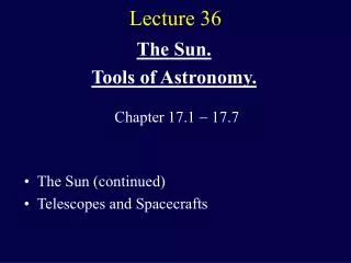
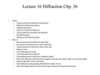
Lecture 16 Diffraction Chp. 36
Lecture 16 Diffraction Chp. 36. Topics Young’s double slit interference experiment Diffraction and the wave theory Single slit diffraction Intensity of single slit diffraction Circular aperture and double slit diffraction Diffraction grating Dispersion and resolving power Demos

Lecture 16 Diffraction Chp. 36
E N D
Presentation Transcript
Lecture 16 Diffraction Chp. 36 • Topics • Young’s double slit interference experiment • Diffraction and the wave theory • Single slit diffraction • Intensity of single slit diffraction • Circular aperture and double slit diffraction • Diffraction grating • Dispersion and resolving power • Demos • laser pointer internal reflected in water flow • laser pointer interference from many reflections • Youngs double slit interference with narrow slits • Newtons rings • Laser diffracted from bead • Laser defracted from single slit • Laser diffracted from single slits of different widths • Now show diffraction and interference together using two slits whose width is a few wavelengths • Measure diameter of hair using laser . • Show diffraction using gratings with different number of lines • Set up discharge tubes and view light through a diffraction grating with telescope
Lens 1 Lens 2 -15 f1 f2 f1 f2 +20 40 30 40 10 Actual ray diagram purple. Dashed lines are virtual rays Thus, the image formed by lens 2 is located 30 cm to the left of lens 2. It is virtual (since i2 < 0). The magnification is m = (-i1/p1) x (-i2/p2) = (-40/40)x(30/-30) =+1, so the image has the same size orientation as the object.
Young’s Double SlitInterference Experiment m=2 y m=1 q m=0 m=1 m=2 D
If you now send the light from the two openings onto a screen, an interference pattern appears, due to differing path lengths from each source • we have constructive interference if paths differ by any number of full wavelengths • destructive interference if difference is half a wavelength longer or shorter Constructive interference Constructive interference Destructive interference
Geometry Path length difference Constructive interference Destructive interference
Destructive interference Constructive interference How do we locate the vertical position of the fringes on the screen? 1) L >> d 2) d >> λ These tell us that θ is small Therefore,
Maxima Minima
Example13E. Suppose that Young’s experiment is performed with blue-green light of 500 nm. The slits are 1.2mm apart, and the viewing screen is 5.4 m from the slits. How far apart the bright fringes? From the table on the previous slide we see that the separation between bright fringes is
Intensity Distribution The electric field at P is sum of E1 and E2. However the Poynting vector is Taking the time average, the intensity I represents the correlation between the two waves. For incoherent light, as there is no definite phase relation between E1 and E2 and cross term vanishes and incoherent sum is
For coherent sources, the cross term is non-zero. In fact, for constructive interference E1 = E2 and I = 4I1 For destructive interference E1 = -E2 and and correlation term = - I1, the total intensity becomes I = I1 -2I1 + I1 = 0 Suppose that the waves emerged from the slits are coherent sinusoidal plane waves. Let the electric field components of the wave from slits 1 and 2 at P be given by We have dropped the kx term by assuming that P is at the origin (x =0) and we have acknowledged that wave E2 has traveled farther by giving it a phase shift (ϕ) relative to E1 For constructive interference, with path difference of δ = λ would correspond to a phase shift of ϕ=2π. This then implies
For constructive interference, with path difference of δ = λ would correspond to a phase shift of ϕ=2π. This then implies Superposition principle allows The intensity I is proportional to the square of the amplitude of the total electric field Then..
• Double slit experiment produces interference pattern if light is coherent For constructive interference: For destructive interference: Intensity:
Newton’s rings are similar, but with curved glass: Why different colors? for any given difference in path length, the condition ΔL =n (m+1/2)λ might be satisfied for some wavelength but not for some other. A given color might or might not be present in the visible image. Pass around Newtons Rings
Diffraction In his 1704 treatise on the theory of optical phenomena (Opticks), Sir Isaac Newton wrote that "light is never known to follow crooked passages nor to bend into the shadow". He explained this observation by describing how particles of light always travel in straight lines, and how objects positioned within the path of light particles would cast a shadow because the particles could not spread out behind the object. True, to a point. On a much smaller scale, when light waves pass near a barrier, they tend to bend around that barrier and spread at oblique angles. This phenomenon is known as diffraction of the light, and occurs when a light wave passes very close to the edge of an object or through a tiny opening, such as a slit or aperture.
Diffraction is a wave effect Interference pattern of light and dark bands around the edge of the object. Diffraction is often explained in terms of the Huygens principle, which states that each point on a wavefront can be considered as a source of a new wave. All points on a wavefront serve as point sources of spherical secondary wavelets. After a time t, the new position of the wavefront will be that of a surface tangent to these secondary wavefronts
In 1818, Augustin Fresnel submitted a paper on the theory of diffraction for a competition sponsored by the French Academy. His theory represented light as a wave, as opposed to a bombardment of hard little particles, which was the subject of a debate that lasted since Newton's day. S.D. Poisson, a member of the judging committee for the competition, was very critical of the wave theory of light. Using Fresnel's theory, Poisson deduced the seemingly absurd prediction that a bright spot should appear behind a circular obstruction, a prediction he felt was the last nail in the coffin for Fresnel's theory. The Fresnel bright spot However, Dominique Arago, another member of the judging committee, almost immediately verified the spot experimentally. Fresnel won the competition, and, although it may be more appropriate to call it "the Spot of Arago," the spot goes down in history with the name "Poisson's bright spot" like a curse
Babinets Complementarity Principle In the diffraction region the intensity is the same whether you have an aperture or opaque disk. You can also replace a slit with a wire or hair strand. A compact disk is an example of a diffraction grating in reflection instead of transmission.
Diffraction by a Single Slit - Locate the First Minima D >> a, rays are parallel Divide the screen into two zones of width a/2 Find the first minima above the midpoint by pairing up rays from the top point of the top zone and the top point of the bottom zone Rays are in phase at the slit but must be out of phase by by λ/2 at screen The path length difference = a/2 sin θ Repeat for other pairs of rays in the upper zone and lower zone: a/2 sin θ = λ/2 a sin θ = λ first minima If we narrow the slit the angle must get bigger - more flaring - - what happens when a = λ?
Diffraction by a Single Slit - Subsequent Minima Repeat the process for paired rays (4) from corresponding points from each of the zones Rays are in phase at the slit but must be out of phase by by λ/2 at screen second minimum Dark fringes - minima
Intensity in Single Slit Diffraction - Derive using phasors - see text alpha where α is just a convenient connection between the angle θ that locates a point on the screen and the light intensity I(θ) I = Im occurs at the central maximum (θ = 0) and ϕ is the phase difference (in radians) between the top and bottom rays from the slit of width a Studying the expression above reveals that the intensity minima occur at Plug this into the expression for α above and we find
Where are the diffraction Maxima? After the central maximum the next maximum occurs about halfway between the first and second minimum.
Exact solution for diffraction maxima Recall To find maxima of a function, take derivative and set equal to 0 Transcendental equation. Solve graphically
Experiment to measure diameter of Teachers hairusing first diffraction minimum. Location of first diffraction minimum hair y1 a D screen
Diffraction by a circular aperture (lens ...) When light from a point source passes through a small circular aperture, it does not produce a bright dot as an image, but rather a diffuse circular disc known as Airy's disc surrounded by much fainter concentric circular rings. This example of diffraction is of great importance because the eye and many optical instruments have circular apertures. First minimum A complex analysis leads to Compare to the relation for a single slit
Resolvability The fact that a lens image is a diffraction pattern is important when trying to resolve distant point objects When the angular separation for two objects is such that the central maximum of one diffraction pattern coincides with the first minimum of the other we have a condition called the Rayleigh’s criterion for resolvability
Example 15E. The two headlights of an approaching automobile are 1.4 m apart. Assume the pupil diameter is 5.0 mm and the wavelength of light is 550 nm. (a) At what angular distance will the eye resolve them and (b) at what distance? (a) (b) s D
Note that as the slit gets wider the central maximum gets smaller -contrary to expectations- Now see what happens when we add more slits.
Diffraction and Interference by a double slit I = I (double slit interference) x I(diffraction)
How many bright interference fringes fall within the central peak of the diffraction envelope? Sample problem 36-5 The idea here is to find the angle where the first minimum occurs of the diffraction envelope. Given 2 refers to double slit interference We have m=0 and m=1,2,3 and 4 on both sides of central peak. Answer is 9
Diffraction Gratings Like the double slit arrangement but with a much greater number of slits, or rulings, sometimes as many as several 1000 per millimeter Light passed through the grating forms narrow interference fringes that can be analyzed to determine the wavelength As the number of rulings increases beyond 2 the intensity plot changes from that of a double slit pattern to one with very narrow maxima (called lines) surrounded by relatively wide dark regions
Diffraction Gratings Principal maxima, where all waves interfere constructively are found with what is now a familiar procedure: each m represents a different line and the integers are called order numbers Rewriting the above we find So the angle to a particular line (say m =3) depends on the wavelength being used
Dispersion In order to distinguish different wavelengths that are close to each other a diffraction grating must spread out the lines associated with each wavelength. Dispersion is the term used to quantify this and is defined as Δθ is the angular separation between two lines that differ by Δλ. The larger D the larger the angular separation between lines of different λ. and D gets larger for higher order (m) and smaller grating spacing (d) It can be shown that
Resolving Power To make lines that whose wavelengths are close together (to resolve them) the line should be as narrow as possible The resolving power is defined by where λavg is the average of the two wavelengths studied and Δλ is the difference between them. Large R allows two close emission lines to be resolved To get a high resolving power we should use as many rulings. It can be shown that
Dispersion and Resolving Power Three gratings illuminated with light of λ=589 nm, m = 1 Highest resolution Highest dispersion
X-Ray Diffraction Spacing between atomic layers in a crystal is the right size for diffracting X-rays; this is now used to determine crystal structure Bragg’s law, θ is Bragg’s angle