Download

1 / 20
0 likes | 2 Vues
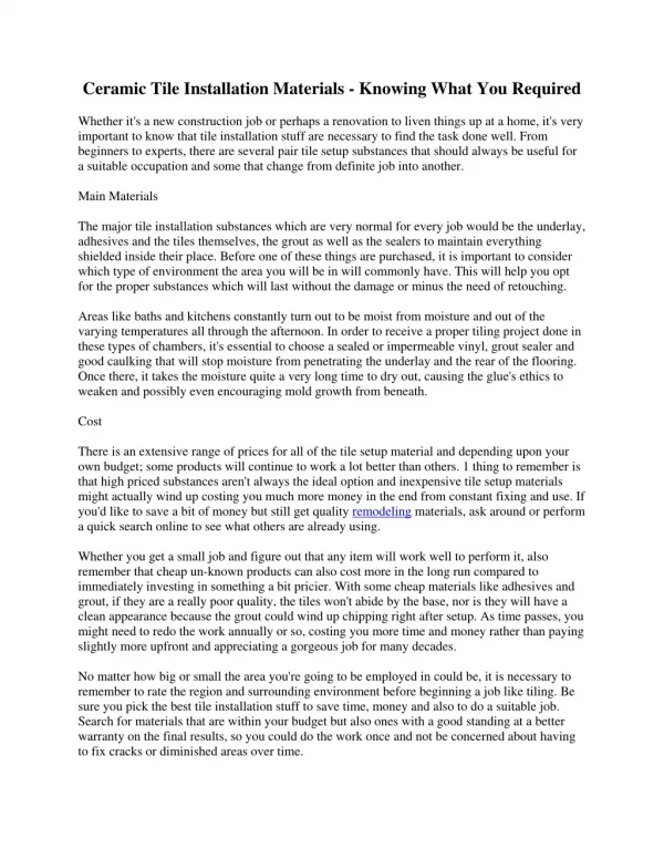
ComfyHome installs Braemar gas ducted heating systems that are designed for Melbourneu2019s changing climate and built to comply with all safety regulations. The company supplies TQ and TQM series heaters that offer zoning control, ceiling or underfloor configurations and compatibility with add-on cooling units. Every system is installed with close attention to heater location, return air grille placement and condensate drainage. From checking gas pressure to adjusting flue connections and thermistor positions.

E N D
INSTALLATION MANUAL Braemar Ecostar TQ3, TQ4, TQ5, TQM5 and TQM6 Gas Ducted Heater Braemar Supernova TQS3, TQS4, TQS5 and TQS6 Gas Ducted Heater
1 TQ3, TQ4, TQ5, TQM5, TQM6, TQS3, TQS4, TQS5, TQS6
THIS HEATER IS TO BE INSTALLED BY AN AUTHORISED PERSON ONLY DO NOT Operate this appliance before reading the instruction booklet. DO NOT Place articles on or against this appliance. DO NOT Use or store flammable materials near this appliance. DO NOT Operate this appliance with panels, covers or guards removed. DO NOT Spray aerosols in the vicinity of this appliance while it is in operation. This Braemar gas ducted heater must be installed in accordance with these instructions, local gas fitting regulations, municipal building codes, electrical wiring regulations, Australian Standard AS/NZS 5601 Gas Installations and any other relevant statutory requirements. This heater must not be installed downstream from an evaporative cooler, air washer or indoor unit of a refrigerated system. This heater is not suitable for installation in a marine environment. This heater is not suitable for outside return air. For external installations, ensure that the heater is located to maintain the minimum flue clearances as specified below and in AS/NZS 5601. Measurement is taken from the edges of the flue terminal. GAS TYPE: GAS CONSUMPTION: Refer label alongside gas inlet. Refer data label on underside of appliance lid. UNPACKING THE HEATER Remove the plastic wrap and cardboard transport cover. Check that the heater model and gas type is as required - model details are provided on the specification label on the end panel of the heater, gas type is given on the label next to the gas inlet. Report any transit damage within 7 days - Do not install the heater if it is damaged. Some points to consider Some points to consider when working on or in a roof What is the best and safest access to the roof and working areas? What condition is the roof in? Should the roof structure and surface be checked? Does the worker have appropriate footwear? Are all power cables/extension leads safe and appropriately rated? Are all ladders, tools and equipment suitable and in good condition? Where ladders are to be used, is there a firm, stable base for them to stand on? Can they be tied or secured in some way at the top? Is there a roof anchor to attach a harness and lanyard to? If so, instruction should be issued for the use of an approved harness or only suitably trained people used. Are all tools and materials being used, prevented from slipping and falling onto a person at ground level? Is the area below the work area suitably protected to prevent people entering this area? Does the work schedule take into account weather conditions, allowing for work to be suspended in high winds, thunder storms/lightning or other types of weather giving wet, slippery surfaces? Is there an on-going safety check system of harnesses, ropes, ladders and access/lifting equipment, and any anchor points on roofs before the commencement of work? Is there a system which prevents employees from working on or in roofs if they are unwell or under the influence of drugs or alcohol? Are there any special conditions to consider i.e. excessive roof pitch, limited ground area, fragile roof,electrical power lines? SAFETY INSTRUCTIONS Employers and Employees Responsibility The installation and maintenance of gas ducted heating units, particularly at height, has the potential to create Occupational Health and Safety issues for those involved. Installers are advised to ensure they are familiar with relevant State and Federal legislation, such as Acts, Regulations, approved Codes of Practice and Australian Standards, which offer practical guidance on these health and safety issues. Compliance with these regulations will require appropriate work practices, equipment, training and qualification of workers. Seeley International provides the following information as a guide to contractors and employees to assist in minimising risk. Risk Assessment A risk assessment of all hazardous tasks is required under legislation. A risk assessment is an essential element that should be conducted before the commencement of work, to identify and eliminate the risk of falls and other risks, or to minimise these risks by implementing control measures. This does not need to be a complicated process - it is a matter of assessing the job to be done and considering what actions are necessary so the person doing the job does not injure themselves. This should be considered in terms of: What are the chances of an incident occurring? What could the possible consequences be? What can be done to reduce, or better still, eliminate the risk? HEATER LOCATION Preferred installation locations Above, below or outside laundry, bathroom, kitchen, garage etc’ Avoid quiet areas: Directly above, below or outside bedrooms, living room, lounge room, dining room etc. SEELEY INTERNATIONAL – INSTALLATION MANUAL 2
HEATER CONFIGURATION Standard External Configuration Reversed External Configuration Increase inlet spigot and duct diameter by 50mm Swapping inlet & outlet panels The heater side panels can be moved to suit a range of installations. To do this: Remove heater top panel. Remove the screws securing the side/end panels that are to be changed. Remove the side panels. Move the inner metal insulation panel to the side or end of the heater to ensure a twin skin sheetmetal layer is maintained. Secure the side panels in their required new positions and re-fit the heater lid. Check that all panels are secure and that screws are tight. IMPORTANT:Increase the diameter of the air inlet spigot and the full run of inlet duct by 50mm to maintain the original air flow rate if it is moved from the open side to the motor side of the room fan. IMPORTANT:The air inlet panel must be fitted to the side of the heater - do not fit the air inlet panel to the end of the heater. Preferred Internal Configuration SPLITTING AND RE-CONNECTING THE HEATER WIRING LOOM PLUG & SOCKET COMBUSTION FAN SUCTION HOSE ROOM FAN END OF HEATER Heaters can be split in two (remove fan box) to assist in lifting heaters into ceilings and moving the heater into position: HEAT EXCHANGER END OF HEATER Splitting the heater Remove the heater top panel. Disconnect the wiring loom at the plug near the top of the centre panels. Disconnect the combustion fan suction hose connected to pressure switches or hose connector depending on heater model. Disconnect the ignition lead, flame sense lead and flame rollout lead from the ICS PCB and feed through the grommet in the centre panel. This is easiest to do with the grommet removed from the panel. Remove the two retaining screws near the top of the centre panels from the room fan end of the heater. Lift the room fan end of the heater to disengage from the locating tabs near the bottom of the centre panel. Separate the two halves of the heater. RETAINING SCREWS PRESSURE SWITCH SUCTION CONNECTIONS ROOM FAN END OF HEATER HEAT EXCHANGER END OF HEATER LOCATING TABS Re-connecting the heater Hook locating tabs into slots near bottom of centre panel. Re-fit 2 retaining screws near top of centre panel. Re-connect the combustionfan suction hose connected to pressure switches or hose connector depending on heater model Re-connect wiring loom plug into socket. Re-connect the ignition lead, flame sense lead and flame rollout lead to the ICS PCB. Ensure any grommets are correcty re-fitted if they were removed. Re-fit heater top panel. RE-FIT 2 RETAINING SCREWS HOOK LOCATING TABS INTO SLOTS ENSURE TABS ARE LOCATED IN SLOTS AT BOTH SIDES TEST THE HEATER ONCE RE-CONNECTION HAS BEEN COMPLETED 3 TQ3, TQ4, TQ5, TQM5, TQM6, TQS3, TQS4, TQS5, TQS6
Reversing combustion flue outlet Non condensing heaters Reversing combustion flue outlet Condensing heaters 1. Disconnect flue fan extension from combustion fan. Remove flue outlet cover from opposite side of heater. 1. Remove side panels from combustion fan end of heater. 2. Twist combustion fan towards burners, lift fan up to separate from heater. 2. Twist combustion fan towards burners, lift fan up to seperate from heater. 3. Turn combustion fan 180 degrees. locate fan feet in 4 round holes in flue pan twisting combustion fan towards burners to lock. 3. Turn combustion fan 180 degrees. locate fan feet in 4 round holes in flue pan twisting combustion fan towards burners to lock. 4. Fit side panels back to heater. 4. Reconnect flue fan extension using silicon to seal connection. Secure flue outlet to side panel using screws previously removed. Fit flue outlet cover to the original outlet hole. BRAEMAR ADD-ON COOLING Ensure ADD-ON COOLER and GAS DUCTED HEATER is selected at the Appliance types screen during system setup on the MagIQtouch Controller to enable the system to operate the Braemar add-on cooling system. Extra Air heaters are designed for use with Braemar add-on cooling. These models include an “X” in their model numbers, eg, TQ3X20, TQM5X20 and TQS5X23. The following points must be taken into account to ensure correct operation of both the refrigerated cooler and the heater. Heater MagIQtouch Controller is required for Braemar add-on cooling functionality. Ensure that the add-on cooling unit is sized correctly to suit the house and the heater. The cooling coil (evaporator) should be installed 1.5 to 2.5m from the heater supply air outlet. To prevent excessive air flow restriction, the ducting between the heater and the cooling coil should be as straight as possible. If bends are required, use the largest bend radius possible. A correctly-sized return air grille with a filter MUST be fitted when installing Braemar add-on cooling. The thermistor must be located after the cooling coil 3m along the duct from the heater outlet, and fitted centrally in the top of the duct. 3 m 1.5 to 2.5 m Return air duct Supply air duct Braemar add-on cooling coil Duct thermistor mounted in duct AFTER add-on cooling coil The “REFRIG 24VAC” terminals on the ICS circuit board in the heater supply 24Vac control voltage to operate the Braemar add-on cooling system. The connection from the heater is via a 24Vac relay to switch the cooling system on and off. A MagIQ link module is required to connect the Braemar Invertair inverter add-on cooling system to the heater. SEELEY INTERNATIONAL – INSTALLATION MANUAL 4
GOOD DUCTING GUIDLINES 1. Based on standard 100 x 300mm floor outlets and 150mm round ceiling outlets. 2. Minimum outlets open to achieve optimum turndown performance. 3. 'X' in model refers to extra-air models - maximum outlets will be reduced when a add-on cooling coil is installed. Correct ductwork installation is critical to ensure correct operation of the heating system, and to prevent premature failure of the fan and/or heat exchanger. The following must be considered: Additional notes: - For heaters suitable for zoning, a minimum of one outlet must remain fully open at all times while the heater is in operation - possible increased noise should be considered if outlets are closed manually. - Where a common zone is installed in a multi MagIQtouch controller or MagIQtouch air sensor zoned system, it can have one or more outlets, and should be located near the return air grille. Supply and return air ducting Ductwork should be adequately sized to suit the heater and installation to prevent excessive system back pressure. Duct run > 6m, increase the diameter of the spigot and duct for the full length of the duct run by 50mm. Duct run > 9m, increase the diameter of the spigot and duct for the full length of the duct run by 100mm. Ductwork should be adequately supported and free from air leaks. Volume dampers are recommended to enable proper balancing of the system. Bends in ducting must be as smooth as possible to minimise restriction to air flow, recommended MINIMUM bend radii are: - 150 to 300 mm duct 1.5 duct diameters - 350 to 400 mm duct 2 duct diameters The minimum RETURN AIR DUCT length should be 3m, and should include a bend to help reduce noise transmission along the duct. Return air grille location Heaters are not suitable for outside return air. Always locate the return air grille in a suitably heated area, central hallways are usually the most suitable. Do not locate in a bathroom or laundry as the moisture present in these rooms may settle on the fan when not in use. The return air grille should be located so that it is unobstructed, for example by carpets, clothing, furniture. Air should not be drawn through areas that are not heated. It is recommended that the return air grille is located at a low level - system performance may be reduced if a high level return air grille is used. N.B Not Recomended above 2.7m. In a single wall control zoned system, the return air grille must be located in the "common" zone, ie, in a zone that cannot be turned off. In a multiple wall control zoned system, where their is no common zone the return air grille must be located as centrally as possible. Outlet registers At least one outlet register must be provided in all areas to be heated. Care should be taken to prevent cold spots, due to excessive draught or insufficient outlets. The normal position of furniture in the home must be considered when locating registers. The type of register should be selected to suit the application: - Registers installed in the floor should discharge sideways. - Registers installed in the ceiling should discharge predominantly vertically. Return air grille sizing Equivalent grille sizes may be used. Fitting a filter is recommended. A filter may generate some air flow noise - the owner should be advised. The owner should be advised to clean the filter every two weeks and replace annually. Return air sizing Recommended Minimum & Maximum system installed outlets Minimum outlets installed per zone Duct connection diameter (mm) Model Minimum grille dimensions (mm) Ceiling 5-8 6-11 7-12 8-13 8-14 10-16 11-18 5-8 6-11 7-12 8-13 8-14 10-16 11-18 11-18 5-8 6-11 7-12 10-16 11-18 5-8 6-11 7-12 10-16 11-18 5-8 6-11 7-12 10-16 11-18 6-11 7-12 6-11 7-12 6-11 7-12 6-11 7-12 Underfloor 6-11 8-14 9-15 10-17 11-18 13-21 14-23 6-11 8-14 9-15 10-17 11-18 13-21 14-23 14-23 6-11 8-14 7-12 13-21 14-23 6-11 8-14 9-15 13-21 14-23 6-11 8-14 9-15 13-21 14-23 8-14 9-15 8-14 9-15 8-14 9-15 8-14 9-15 Ceiling NA NA NA NA NA NA NA 1 2 2 2 2 3 3 3 1 2 2 3 3 1 2 2 3 3 1 2 2 3 3 2 2 2 2 2 2 2 2 Underfloor NA NA NA NA NA NA NA 2 3 3 3 3 4 4 4 2 3 3 4 4 2 3 3 4 4 2 3 3 4 4 3 3 3 3 3 3 3 3 No filter 500 x 400 500 x 400 600 x 400 600 x 400 750 x 400 750 x 400 900 x 400 500 x 400 500 x 400 600 x 400 600 x 400 750 x 400 750 x 400 900 x 400 900 x 400 500 x 400 500 x 400 600 x 400 750 x 400 900 x 400 500 x 400 500 x 400 600 x 400 750 x 400 900 x 400 500 x 400 500 x 400 600 x 400 750 x 400 900 x 400 500 x 400 600 x 400 500 x 400 600 x 400 500 x 400 600 x 400 500 x 400 600 x 400 With filter 750 x 400 750 x 400 900 x 400 900 x 400 1000 x 400 1000 x 400 1200 x 400 750 x 400 750 x 400 900 x 400 900 x 400 1000 x 400 1000 x 400 1200 x 400 1200 x 400 750 x 400 750 x 400 900 x 400 1000 x 400 1200 x 400 750 x 400 750 x 400 900 x 400 1000 x 400 1200 x 400 750 x 400 750 x 400 900 x 400 1000 x 400 1200 x 400 750 x 400 900 x 400 750 x 400 900 x 400 750 x 400 900 x 400 750 x 400 900 x 400 TQ315 TQ320 TQ3X20 TQ325 TQ3X25 TQ330 TQ3X30 TQ415 TQ420 TQ4X20 TQ425 TQ4X25 TQ430 TQ4X30 TQ435 TQ516 TQ523 TQ5X23 TQ532 TQ5X32 TQM516 TQM520 TQM5X20 TQM532 TQM5X32 TQM618 TQM623 TQM6X23 TQM632 TQM6X32 TQS320 TQS3X20 TQS420 TQS4X20 TQS523 TQS5X23 TQS623 TQS6X23 300 300 350 350 350 350 400 300 300 350 350 350 350 400 400 300 300 350 350 400 300 300 350 350 400 300 300 350 350 400 300 350 300 350 300 350 300 350 5 TQ3, TQ4, TQ5, TQM5, TQM6, TQS3, TQS4, TQS5, TQS6
ZONING - TQ4, TQ5, TQM5, TQM6, TQS3, TQS4, TQS5, TQS6 Kits and parts required for zoning 24V zone kit P/No 094939 - to suit 24Vac zone dampers: Kit includes - zone control board, communication cables, connection wires, 24Vac transformer. 240V zone kit P/No 094922 - to suit 240Vac zone dampers: Kit includes - zone control board, communication cables, connection wires. Multiple MagIQtouch Controllers or MagIQtouch Air Sensors - one MagIQtouch Controller is supplied with each TQ4 & TQ5 installation accessories kit - an additional MagIQtouch Controller or MagIQtouch Air Sensor & loom is required for each additional zone. MagIQtouch Controller/loom kit P/No 075587. MagIQtouch Air Sensor/loom kit P/No 094328. Zone dampers and suitable wiring (not supplied by Seeley International) TQ4, TQ5, TQM5, TQM6, TQS3, TQS4, TQS5, TQS6 model heaters can be installed and set-up to independently heat different areas within the home. Zoning options include the following. Zones, Single MagIQtouch Controller: Each zone is controlled independently from a single MagIQtouch Controller. The MagIQtouch Controller must be located in a "common zone", ie, a zone that cannot be turned off, and that includes the return air grille. Zones, Single MagIQtouch Controller + Master MagIQtouch Air Sensor: This option can be used where the desired location for the MagIQtouch Controller is not the best location to sense temperature. A MagIQtouch Air Sensor can be installed with a single MagIQtouch Controller as a “Master Air Sensor” As the “Master” temperature sensing device, it overrides the sensor located inside the MagIQtouch Controller itself. The MagIQtouch Air Sensor must be located in a "common zone", ie, a zone that cannot be turned off, and that includes the return air. In this scenario, the MagIQtouch Controller will operate in relation to temperature detected by the MagIQtouch Air Sensor. CLEARANCES AND CONNECTIONS Minimum flue clearances for external heaters 75mm From a drain pipe or soil pipe. 300mm From any other flue terminal, cowl, or combustion air intake. Below eaves, balconies, and other projections. Horizontally from an openable window, door, non-mechanical air inlet, or any other opening into a building with the exception of sub-floor ventilation. Zones, Master MagIQtouch Controller + MagIQtouch Air Sensors: MagIQtouch Air Sensors can be installed in zoned systems instead of a Slave MagIQtouch Controller. In this scenario the Master MagIQtouch Controller operates the zoned system according to temperatures detected by the MagIQtouch Air Sensor(s) installed in each individual zone. This allows zones to be set to different desired temperatures. 500mm From electricity meter or fuse box. From a return wall or external corner. Horizontally from any building structure or obstruction facing a terminal. 1000mm From a gas meter. From a mechanical air inlet, including a spa blower. Vertically below an openable window, non-mechanical air inlet, or any other opening into a building with the exception of sub-floor ventilation. Zones, Master MagIQtouch Controller + Slave MagIQtouch Controllers: Each zone is controlled independently from its own MagIQtouch Controller - this allows zones to be set at different temperatures, and to be controlled from within the zone. Each zone that has its own MagIQtouch Controller must include a zone damper. 1500mm Horizontally in the direction of discharge from an openable window, door, non-mechanical air inlet, or any other opening into a building with the exception of sub-floor ventilation. Refer also: AS/NZS 5601 Gas Installations In each case zone dampers must be installed into selected duct runs to allow the air flow to a zone to be turned on or off. Refer to installation manual provided with the MagIQtouch Zone Control for detailed instructions on installing the above zoning options. Hints for zoned systems Talk to the customer to get an understanding of their requirements. Allow for an outlet near the return air to prevent drafts and cold spots. For Single MagIQtouch Controller or Single MagIQtouch Controller + Master MagIQtouch Air Sensor systems ensure that the COMMON zone is always heated, even if it is only asmall air flow. The common zone must include a return air grille. Explain to the customer the function of the return air duct, and the need for a clear airpath to the return air grille - air cannot travel through closed doors. DO NOT in any way obstruct the flow of return air. For Single MagIQtouch Controller systems position the wall control in the COMMON zone. Zone fan speeds Zone fan speeds must be set to ensure an appropriate air flow for each zone. If the fan speed is set too high for the number of outlets this may cause high air flow noise and will not be covered under warranty. If the fan speed is set too low for the number of outlets this may cause poor heating performance, and may cause cycling due to thermistor or thermal limit switch operation. SEELEY INTERNATIONAL – INSTALLATION MANUAL 6
GAS CONNECTION MAGIQTOUCH CONTROLLER OR MAGIQTOUCH AIR SENSOR LOCATION If bottled gas is being used to supply the ducted gas heater, then we strongly recommend that an UPSO regulator be installed in the gas line upstream of the unit. Damage can occur to the ducted gas heating unit if it is operated when the gas supply has run out or is running low. A correctly installed UPSO regulator in the gas line will protect the ducted gas heating unit from such damage (and may also protect other gas appliances in the house), because it will turn off the gas supply if the gas runs out or runs too low.” All gas supply piping must be installed by a licensed gas fitter in accordance with Standard AS/NZS 5601 Gas Installations. Gas connection point: All models - 3/4" BSP female flare nut. Gas supply piping must be sized to ensure a minimum gas pressure of 1.13 kPa for natural gas appliances or 2.75 kPa for propane appliances at the inlet to the heater with the heater and all other gas appliances operating at maximum gas rate. Detailed pipe sizing information is contained in Standard AS/NZS 5601 Gas Installations. The maximum gas rate for the heater is located on the specification label on the underside of the heater lid. An AGA approved gas cock/manual shut-off valve must be fitted in the gas supply line adjacent to the heater (outside the heater cabinet) to enable isolation of the heater for maintenance and/or servicing. Ensure that all air is purged out of the gas line. Ensure that there are no gas leaks. MagIQtouch Controller Refer to the installation manual provided with the MagIQtouch Controller for mounting and installation instructions. MagIQtouch Air Sensor Refer to the installation manual provided with the MagIQtouch Air Sensor for mounting and installation instructions. The MagIQtouch Controller is required to obtain full functionality with Braemar heater, including zoning (All heaters except TQ3 models) and evaporative or refrigerated cooler operation. With the addition of multiple optional MagIQtouch Zone Control kits and MagIQtouch Link Module kits, heaters can be used with up to 10 controllers with each controller controlling its own independent zone. MAGIQTOUCH CONTROLLER CONNECTION Connect one end of the MagIQtouch controller cable to terminal labeled wall control on the ICS. Gas Connection All Models ELECTRICAL CONNECTION Electrical wiring & fittings must be installed by a licensed Electrician. Seeley International recommends that all Braemar gas ducted heaters are wired with a dedicated circuit from the distribution board with a separate circuit breaker. Wiring must be installed in accordance with the relevant electrical standards & regulations. The electrical supply must be 240V 50Hz. A conventional 10A 3-pin 240V GPO must be fitted adjacent to the heater. Ensure that the polarity of the power supply is correct. If the supply cord is damaged, it must be replaced by the manufacturer, its service agent or similarly qualified persons in order to avoid a hazard. 24V Manual Digital Controller Refer to the installation manual provided with the 24V Manual Controller for mounting and installation instructions. UNDER NO CIRCUMSTANCES SHOULD DOUBLE ADAPTERS, POWER BOARDS OR EXTENSION LEADS BE USED. All heaters can all be used with a standard 2-wire type manual digital controller. Connect a low voltage 2-wire loom between the Manual controller and "T STAT" on the ICS circuit board. Note that with Braemar TQ, TQM, TQS series heaters zoning, evaporative or add-on cooling operation and room fan speed adjustment is not possible with these thermostats. Active Neutral IMPORTANT ENSURE THAT POLARITY OF POWER SUPPLY IS CORRECT Earth 7 TQ3, TQ4, TQ5, TQM5, TQM6, TQS3, TQS4, TQS5, TQS6
heat shield Side wall 077420 077420 077420 077420 077420 077420 077420 077420 077420 077420 077420 077420 077420 077420 077420 077420 077420 077420 077420 077420 077420 077420 077420 077420 NA NA NA NA NA NA NA NA NA NA NA NA NA NA kit Flue guard 079073 079073 079073 079073 079073 079073 079073 079073 079073 079073 079073 079073 079073 079073 079073 079073 079073 079073 079073 079073 079073 079073 079073 079073 NA NA NA NA NA NA NA NA NA NA NA NA NA NA kit 300 mm 076348 076348 076348 076034 076348 076348 076034 076034 076348 076034 076348 076034 076034 076348 076034 076348 076348 076034 076034 076348 076386 076348 076034 076348 077277 077277 076348 076348 076386 077277 076348 077277 076348 076386 076386 076386 076386 076386 Flashing kits 150 mm 076331 076331 076331 075990 076331 076331 075990 075990 076331 075990 076331 075990 075990 076331 075990 076331 076331 075990 075990 076331 076362 076331 075990 076331 077260 076331 077260 076331 076362 077260 076331 077260 076331 076362 076362 076362 076362 076362 Flush to 076898 076898 076898 076898 076898 076898 076898 076898 076898 076898 076898 076898 076898 076898 076898 076898 076898 076898 076898 076898 076898 076898 076898 076898 076898 076898 076898 076898 076898 076898 076898 076898 076898 076898 076898 076898 076898 076898 wall MagIQtouch air sensor & Loom 094328 094328 094328 094328 094328 094328 094328 094328 094328 094328 094328 094328 094328 094328 094328 094328 094328 094328 094328 094328 094328 094328 094328 094328 094328 094328 094328 094328 094328 094328 094328 094328 094328 094328 094328 094328 094328 094328 Controller & Loom MagIQtouch 075587 075587 075587 075587 075587 075587 075587 075587 075587 075587 075587 075587 075587 075587 075587 075587 075587 075587 075587 075587 075587 075587 075587 075587 075587 075587 075587 075587 075587 075587 075587 075587 075587 075587 075587 075587 075587 075587 094922 094922 094922 094922 094922 094922 094922 094922 094922 094922 094922 094922 094922 094922 094922 094922 094922 094922 094922 094922 094922 094922 094922 094922 094922 094922 094922 094922 094922 094922 094922 240Vac NA NA NA NA NA NA NA Zoning kits 094939 094939 094939 094939 094939 094939 094939 094939 094939 094939 094939 094939 094939 094939 094939 094939 094939 094939 094939 094939 094939 094939 094939 094939 094939 094939 094939 094939 094939 094939 094939 24Vac NA NA NA NA NA NA NA - Zone dampers are not supplied by Seeley International and are not included in any zone kit. External Underfloor - The MagIQtouch Controller is required to enable maximum heater functionality. 075518 075518 075556 075556 075518 075518 075518 075525 075563 075556 075556 075563 075518 075525 075518 075518 075563 075563 075525 075518 075563 075556 075518 075518 075518 075563 075563 075556 075518 075563 075518 075518 075518 075525 075518 075563 075556 075525 MagIQtouch controller 075501 075501 075556 075532 075556 075501 075501 075501 075532 075570 075556 075556 075570 075501 075532 075501 075501 075570 075570 075532 075501 075570 075556 075501 075501 075501 075570 075570 075556 075501 075501 075570 075501 075532 075501 075501 075570 075556 External Underfloor Internal 075006 075006 075006 075006 075525 075006 075006 075006 075006 075525 075563 075006 075006 075006 075563 075525 075006 075006 075563 075563 075525 075006 075563 075006 075006 075006 075006 075563 075563 075006 075006 075563 075006 075006 075525 075006 075006 075563 Installation kits 077352 077352 077352 077352 077352 077352 077352 NA NA NA NA NA NA NA NA NA NA NA NA NA NA NA NA NA NA NA NA NA NA NA NA NA NA NA NA NA NA NA Manual control 077291 077291 077291 077291 077291 077291 077291 NA NA NA NA NA NA NA NA NA NA NA NA NA NA NA NA NA NA NA NA NA NA NA NA NA NA NA NA NA NA NA Internal 077284 077284 077284 077284 077284 077284 077284 NA NA NA NA NA NA NA NA NA NA NA NA NA NA NA NA NA NA NA NA NA NA NA NA NA NA NA NA NA NA NA TQM5X30 TQM5X20 TQM6X23 TQM6X32 TQS4X20 TQS6X23 TQM530 TQS3X20 TQS5X23 TQM632 TQM520 TQM623 TQM516 TQM618 TQ4X30 TQ5X23 TQ4X25 TQ3X30 TQ3X20 TQ5X32 TQ4X20 TQ3X25 TQS420 TQS623 TQS320 TQS523 TQ420 TQ532 TQ430 TQ415 TQ325 TQ523 TQ516 TQ425 TQ330 TQ320 TQ435 TQ315 Model KITS Notes: SEELEY INTERNATIONAL – INSTALLATION MANUAL 8
HEATER DIMENSIONS Dimension (mm) Heater Model J K L M N P Q R A B C D E F G H TQ3 and TQ4 models 202 383 202 383 202 383 200 415 200 415 202 383 202 383 200 415 TQ315, TQ415 TQ320, TQ420 TQ325, TQ425 TQ330, TQ430 TQ435 TQ3X20, TQ4X20 TQ3X25, TQ4X25 TQ3X30, TQ4X30 385 385 385 510 510 385 385 510 660 660 660 660 660 660 660 660 574 574 574 557 557 574 574 557 25 25 25 25 25 25 25 25 770 770 770 880 880 770 770 880 685 685 735 767 767 735 735 767 395 395 415 415 415 415 415 415 244 244 244 240 240 244 244 240 300 300 350 350 400 350 350 400 555 555 555 555 555 555 555 555 332 332 332 330 330 332 332 330 695 695 695 687 687 695 695 687 625 625 625 609 609 625 625 609 55 55 55 83 83 55 55 83 TQ5 models 765 765 703 765 703 TQ516 TQ523 TQ532 TQ5X23 TQ5X32 385 385 510 385 510 660 660 660 660 660 574 574 557 574 557 25 25 25 25 25 1150 1150 1165 1150 1165 535 535 504 535 504 1067 1067 1054 1117 1054 395 395 415 415 415 244 244 240 244 240 300 300 350 350 400 578 578 578 578 578 670 670 636 670 636 1003 1003 980 1003 980 625 625 609 625 609 55 55 83 55 83 TQM5 models 383 383 415 383 415 TQM516 TQM520 TQM530 TQM5X20 TQM5X30 385 385 510 385 510 660 660 660 660 660 574 574 557 574 557 25 25 25 25 25 770 770 880 770 880 202 202 200 202 200 685 685 767 735 767 395 395 415 415 415 244 244 205 244 205 300 300 350 350 400 555 555 555 555 555 332 332 330 332 330 695 695 687 695 687 625 625 609 625 609 55 55 83 55 83 TQM6 models 765 765 703 765 703 TQS models 383 765 383 765 TQM618 TQM623 TQM632 TQM6X23 TQM6X32 385 385 510 385 510 660 660 660 660 660 574 574 557 574 557 25 25 25 25 25 1150 1150 1165 1150 1165 535 535 504 535 504 1067 1067 1054 1117 1054 395 395 415 415 415 244 244 240 244 240 300 300 350 350 400 578 578 578 578 578 670 670 636 670 636 1003 1003 980 1003 980 625 625 609 625 609 55 55 83 55 83 TQS320, TQS420 TQS523, TQS623 TQS3X20, TQS4X20 TQS5X23, TQS6X23 385 385 385 385 660 660 660 660 574 574 574 574 25 25 25 25 770 1150 770 1150 202 535 202 535 685 1067 735 1117 395 395 415 415 244 244 244 244 300 300 350 350 555 578 555 578 332 670 332 670 695 1003 695 1003 625 625 625 625 55 55 55 55 Heaters Heaters R N TQ516 TQ523 TQ5X23 TQ532 TQ5X32 TQM618 TQM623 TQM6X23 TQM632 TQM6X32 TQS523 TQS5X23 TQS623 TQS6X23 TQ315 TQ320 TQ3X20 TQ325 TQ3X25 TQ330 TQ3X30 TQ415 TQ420 TQ4X20 TQ425 TQ4X25 TQ430 TQ4X30 TQ435 TQM516 TQM520 TQM5X20 TQM532 TQM5X32 TQS320 TQS3X20 TQS420 TQS4X20 N R Q FLUE M Q FLUE CONNECTION M CONNECTION ELECTRICAL ENTRY [1] P P ELECTRICAL ENTRY [1] E E F A A F D D GAS ENTRY B B GAS ENTRY C C L L L L J J K K Note 1: Alternative electrical entry points can be used - knockouts are provided. G G Note 1: Alternative electrical entry points can be used - knockouts are provided. AIR OUTLET AIR INLET AIR OUTLET AIR INLET H H 9 TQ3, TQ4, TQ5, TQM5, TQM6, TQS3, TQS4, TQS5, TQS6
Dimension (mm) EXTERNAL INSTALLATION Heater Model Concrete slab Wall opening A TQ3 and TQ4 models 400 400 400 550 550 400 400 550 B C D Heater base TQ315, TQ415 TQ320, TQ420 TQ325, TQ425 TQ330, TQ430 TQ435 TQ3X20, TQ4X20 TQ3X25, TQ4X25 TQ3X30, TQ4X30 800 800 800 900 900 800 800 900 460 460 460 460 460 460 460 460 760 760 760 870 870 760 760 870 Construct the heater base and prepare wall opening to the dimensions shown in the table below. ENSURE THAT THE BASE IS LEVEL IN BOTH DIRECTIONS. Heater is approved for installation against a wall. Refer to above kits tabel for flashing kit part numbers. TQ5 models TQ516 TQ523 TQ532 TQ5X23 TQ5X32 400 400 550 400 550 1200 1200 1200 1200 1200 460 460 460 460 460 1160 1160 1160 1160 1160 D TQM5 models 400 400 550 400 550 C TQM516 TQM520 TQM530 TQM5X20 TQM5X30 800 800 900 800 900 460 460 460 460 460 760 760 870 760 870 Lintel TQM6 models 400 400 550 400 550 TQS models 400 400 400 400 TQM618 TQM623 TQM632 TQM6X23 TQM6X32 1200 1200 1200 1200 1200 460 460 460 460 460 1160 1160 1160 1160 1160 Concrete slab B TQS320, TQS420 TQS523, TQS623 TQS3X20, TQS4X20 TQS5X23, TQS6X23 800 1200 800 1200 460 460 460 460 760 1160 760 1160 A Flue connection - Non modulating heaters Flue connection - Modulating heaters Heaters TQ315 TQ320 TQ3X20 TQ325 TQ3X25 TQ330 TQ3X30 TQ415 TQ420 TQ4X20 TQ425 TQ4X25 Heaters TQM516 TQM520 TQM5X20 TQM530 TQM5X30 TQS420 TQS4X20 TQ430 TQ4X30 TQ435 TQS320 TQS3X20 Heater flue outlet Heater flue outlet spigot Fix in place with screw External flue terminal (stainless steel) External flue terminal POWDER-COATED DIE CAST VERSION Push flue terminal onto heater flue outlet spigot. Align hole in flue terminal spigot with hole in heater flue outlet, and secure in place with screws provided in installation kit. Powder coated steel flue terminal and starter collars are included in external installation accessories kit. Larger starter collars (400mm) required for the X30/X32 units are supplied inside the heater fan inlet. A flue guard kit is available for external installations.P/No 079073. Attach powder coated die cast flue terminal to heater over flue outlet, fixing in place using screws supplied. Powder coated die cast flue terminal and starter collars are included in external installation accessories kit. Larger starter collars (400mm) required for the X-Air units are supplied inside the heater fan inlet. A flue guard kit is available for external installations. P/No 079073. Heaters TQ516 TQ523 TQ5X23 TQ532 TQ5X32 Plastic vent cowl and condensate drain elbow are supplied in external installation accessories kit. Heaters TQM618 TQM623 TQM6X23 TQM632 TQM6X32 TQS523 TQS5X23 TQS623 TQS6X23 A flue terminal and condensate drain elbow are supplied in TQM/TQS6 external installation accessories kit. P/No 075570 Seal flue and condensate drain connections with silicone sealant or PVC primer and solvent cement. Seal flue and condensate drain connections with silicone sealant or PVC primer and solvent cement. Fix flue in place with screw Fix flue in place with screw Plastic vent cowl. TQ5 ONLY External flue terminal Check that upper transit plug is secure Check that upper transit plug is secure Terminate condensate drain in a suitable location Terminate condensate drain in a suitable location Remove & discard lower transit plug Remove & discard lower transit plug Condensate drain elbow Condensate drain elbow SEELEY INTERNATIONAL – INSTALLATION MANUAL 10
Flue 750 Min Isolation valve CEILING INSTALLATION Heater platform and clearances A = 385 or 510 Depends on model. See page 9. Gas supply ROOM FAN END OF HEATER HX END OF HEATER The heater must be mounted on a platform to enable access for servicing and maintenance. Minimum clearances must be maintained around the heater as shown. A 600mm wide walkway must be provided from the ceiling access point to the appliance. Permanent artificial lighting must be provided at the appliance with the switch adjacent to the access opening. Check that the section of the roof in which the heater is to be installed is capable of supporting the additional load of the heater. Where possible, the heater should be mounted over a load-bearing wall so that it is not being supported by the ceiling joists alone. Check that the heater does not cause deformation of any part of the building structure. A HEATER LOCATION AVOID QUIET AREAS: - Above bedrooms, living room, lounge room, dining room etc PREFERRED LOCATIONS: - Above laundry, bathroom, kitchen, garage etc’ E E = 770, 880,1160 Depends on model - see “Heater Dimensions” page 750 Min Ensure 200mm minimum clearance above heater Service/maintenance platform - 19mm particle board or equivalent Heaters TQ315 TQ320 TQ3X20 TQ325 TQ3X25 TQ330 TQ3X30 TQ415 TQ420 TQ4X20 TQ425 TQ4X25 TQ430 TQ4X30 TQ435 TQS320 TQS3X20 TQM516 TQM520 TQM5X20 TQM530 TQM5X30 TQS420 TQS4X20 Flue connection - TQ3, TQ4, TQM5, TQS3, TQS4 This heater must be flued using AGA approved 100 mm metal flue pipe. External joins - socket must face downwards. Internal joins - socket must face upwards. Socket joins must be adequately sealed - eg, Silastic 747 silicone sealant. Twin-wall metal flue must be used for any part of the flue that is not readily accessible. Twin-wall metal flue is recommended for flue exceeding 2m in length. 100 mm flue cowl AGA approved 500 mm to nearest part of roof 100 mm flue pipe Single or twin skin AGA approved 200 mm minimum for servicing Permanent Platform 19 mm particle board or equivalent Flue lengths: - Maximum vertical: 4.8m - Maximum horizontal: 4m - Maximum total: 6m Flue bends: - Maximum 2 x 90o elbows - 2 x 45o bends = 1 x 90o elbow 100 mm 90o bend Fire resistant base NOT REQUIRED 90o bend and starter collars are included in internal installation accessories kit. Larger starter collars (400mm) required for the X30,X32 & 35kW units are supplied inside the heater fan inlet. Fitting the flue Fit flue elbow inside socket on heater Fit flue pipe inside socket on flue elbow Fit flue socket to heater Flue & condensate drain connection Heaters TQ516 TQ523 TQ5X23 TQ532 TQ5X32 TQM618 TQM623 TQM6X23 TQM632 TQM6X32 TQS523 TQS5X23 TQS623 TQS6X23 SEAL CONNECTIONS: Seal flue and condensate drain connections using silicone sealant or PVC primer and solvent cement. INSULATE DRAIN LINE: Fit insulation (eg, Armaflex) over full length of condensate drain line in sub-zero climates Condensate drain tee assembly: The flexible tube supplied as part of the condensate drain tee assembly is intended to prevent excessive strain of the condensate drain fittings when fitting and securing the rigid PVC drain line. It is not designed to take the place of a 90o bend. 100mm plastic DWV vent cowl Vent cowl, condensate drain tee assembly, flue drain elbow and flue drain hose are supplied in internal installation accessories kit. Fix flue elbow in place with screw Minimum 500mm to nearest part of roof Flue drain elbow 100mm plastic DWV pipe Flue drain hose Remove & discard flue transit plug & one drain transit plug 200mm minimum for maintenance and servicing access Condensate drain tee assembly Secure condensate drain to flexible tube using hose clamp supplied 100mm plastic DWV M-F elbow Terminate condensate drain in a suitable location Seal remaining drain transit plug located on the opposite side of the heater to condensate drain using silicone sealant or PVC primer and solvent cement. 11 TQ3, TQ4, TQ5, TQM5, TQM6, TQS3, TQS4, TQS5, TQS6
UNDER-FLOOR INSTALLATION There is to be a minimum clearance of 200mm between the lowest part of the floor structure and any part of the heater. The heater is to be located within 2m of the access opening, or there is to be a minimum clearance of 1.2m between the lowest part of the floor structure. and the ground level, maintained from the access opening to the appliance. The heater must be mounted on a level concrete base of at least 50mm thick as per the slab dimensions or suspended above the ground. Fixed artificial lighting must be provided at the heater, with the switch located adjacent to the access opening. Flue connection - Non modulating heaters Flue connection - modulating heaters Heaters TQM516 TQM520 TQM5X20 TQM530 TQM5X30 TQS420 TQS4X20 Heaters TQ315 TQ320 TQ3X20 TQ325 TQ3X25 TQ330 TQ3X30 TQ415 TQ420 TQ4X20 TQ425 TQ4X25 TQ430 TQ4X30 TQ435 TQS320 TQS3X20 External flue cover kit available. P/No 079073. External flue cover kit available. P/No 079073. Flue to terminate outside building External flue terminal (Die cast) Pre drill a 5mm hole in the powder coated die cast flue terminal Flue to terminate outside building FLOOR FLOOR External flue terminal (Metal Powder coated) Light switch must be adjacent to access opening Light switch must be adjacent to access opening 200mm minimum for servicing 200mm minimum for servicing Attach flue terminal to flue, fixing in place with screw. External Wall External Wall FLUE FLUE HEATER With timber side wall Use side wall flue heat shield kit P/No 077420. With timber side wall Use side wall flue heat shield kit P/No 077420. HEATER DUCT DUCT concrete base concrete base Heaters TQM618 TQM623 TQM6X23 TQM632 TQM6X32 TQS523 TQS5X23 TQS623 TQS6X23 Heaters SEAL CONNECTIONS: Seal flue and condensate drain connections using silicone sealant or PVC primer and solvent cement. SEAL CONNECTIONS: Seal flue and condensate drain connections using silicone sealant or PVC primer and solvent cement. TQ516 TQ523 TQ5X23 TQ532 TQ5X32 INSULATE DRAIN LINE: Fit insulation (eg, Armaflex) over full length of condensate drain line in sub-zero climates. INSULATE DRAIN LINE: Fit insulation (eg, Armaflex) over full length of condensate drain line in sub-zero climates. Vent cowl, condensate drain tee assembly, flue drain elbow and flue drain hose are supplied in TQ5 internal installation accessories kit. P/No 075525 Flue terminal, condensate drain tee assembly, flue drain elbow and flue drain hose are supplied in installation accessories kits. P/No 075563 Fix flue pipe in place with screw Fix flue pipe in place with screw Rise: Rise: Minimum 10mm/m for horizontal runs Minimum 10mm/m for horizontal runs Flue drain elbow Flue drain elbow Flue drain hose Vent cowl Flue drain hose Remove & discard transit plugs Remove & discard transit plugs Terminate condensate drain in a suitable location Terminate condensate drain in a suitable location Condensate drain tee assembly Condensate drain tee assembly SEELEY INTERNATIONAL – INSTALLATION MANUAL 12
FLUE SYSTEM & CONDENSATE DRAIN TQ5, TQM6, TQS5, TQS6 Flue system Braemar TQ5, TQM6, TQS5, TQS6 heaters must be flued using 100mm DWV plastic pipe and components complying with AS1260. The flue terminal on the side of the heater is designed to accept either the male end of a 100mm DWV M-F elbow, or 100mm DWV pipe. Connections The connection to the heater, and all other joins in the flue and condensate drain system must be sealed to prevent leakage of condensate. USE SILICONE SEALENT OR PVC SOLVENT CEMENT AND PRIMER FOR ALL CONNECTIONS. Flue treminal The flue system must be terminated to outside with a 100mm DWV vent cowl as shown in the installation diagrams. This is supplied in both internal and external installation accessories kits. Maximum flue length Maximum vertical rise : 5 metres, Maximum total flue length 12 metres, Maximum number of bends 4 x 90° (2 x 45° bends = 1 x 90°). Condensate drain Use either 15mm rigid PVC pressure pipe or 20mm rigid PVC electrical conduit. Do not allow condensate to be discharged over electrical connections, earth stakes, concrete paths, copper pipes or metallic roofs. Do not discharge directly into guttering. Condensate can be discharged into a vent pipe via a tundish and self-sealing device, or into a vertical section of a downpipe via a tundish. Condensate drain must run down hill from connection point on heater to point of discharge - do not allow any part to run up-hill. Condensate drain must be well supported. Do not allow condensate to be discharged into any potable water system or potable water system collection point. Fit insulation (eg, Armaflex)over full length of condensate drain line in sub-zero climates. INSTALLING THE DUCT THERMISTOR TQ4, TQ5, TQM5, TQM6, TQS3, TQS4, TQS5, TQS6 Thermistor location is CRITICAL to the correct operation of the heater The outlet air temperature thermistor must be installed in the outlet air duct approximately 3 metres of duct length from the heater outlet. On systems with more than 1 outlet duct from the heater the thermistor must be located in the duct that always has air flow. Thermistor must be installed in a duct that always has airflow, and never in a duct that can be turned off in a zoned system. To Install the Thermistor Drill a 12mm hole in either the BTO or duct ensuring 3 metres of duct length from the heater outlet. Feed the thermistor and bracket through the grommet in the side of the heater. Insert the bracket into the hole in either the BTO or duct and screw of securely tape into place. Seal the hole. Coil and secure any excess thermistor cable outside the heater. Tape Screw Thermistor bracket Thermistor 12mm hole 3 m Duct or BTO Return air Heated air duct 3 m Return air Heated air duct Thermistor must be installed in a duct that always has airflow 13 TQ3, TQ4, TQ5, TQM5, TQM6, TQS3, TQS4, TQS5, TQS6
COMMISSIONING - INSTALLER OR COMMISSIONING AGENT Installation checks Check for gas leaks - rectify any leaks found. - Natural Gas 1.13kPa - Propane 2.75kPa Check for gas leaks - rectify any leaks found. Check that the flue system is connected, sealed and installed with appropriate clearances. Check that Controller is wired correctly and installed in a suitable location. Check that the heater is level in both directions (critical for TQ5, TQM6, TQS5, TQS6 heaters to allow correct drainage of condensate). Gas pressure checks Connect a manometer to the outlet pressure test point on the gas valve. Start heater as described in Owner’s Manual. Wait 30 seconds after heater lights to ensure heater has reached high gas rate. Commissioning continued Non modulating heaters Commissioning continued Modulating heaters Single stage gas valve TQS523 TQS5X23 TQS623 TQS6X23 TQM5X30 TQM516 TQM520 TQM5X20 TQM530 TQM632 TQM6X32 TQS420 TQS4X20 TQ3X25 TQ330 TQ3X30 TQ315 TQ320 TQ3X20 TQ325 TQM618 TQM623 TQM6X23 Check high gas High gas pressure: - Natural Gas Nominal 875 Pa (825 to 925 Pa) - Propane Nominal 2250 Pa (2050 to 2450 Pa) Adjust only if outside this range USE LARGE HIGH GAS ADJUSTMENT SCREW - hold small adjustment screw still Run heater and check pressure at outlet test point, adjust if necessary: - All natural gas models: 875 +/- 50 Pa OUTLET PRESSURE TEST POINT REGULATOR ADJUSTMENT COVER Check low gas Gas Out Remove one lead from modulating coil (LOW VOLTAGE, 0-17 Vdc) Low gas pressure: - Natural Gas Nominal 100 Pa (90 to 110 Pa) - Propane Nominal 180 Pa (170 to 190 Pa) Adjust only if outside this range USE SMALL LOW GAS ADJUSTMENT SCREW - hold large adjustment screw still INLET PRESSURE TEST POINT Two stage gas valve TQ415 TQ420 TQ4X20 TQ425 TQ4X25 TQ430 TQ4X30 TQ435 TQ516 TQ523 TQ5X23 TQ532 TQ5X32 TQS320 TQS3X20 Re-check high gas Re-connect lead to modulating coil High gas pressure: - Natural Gas Nominal 875 Pa (825 to 925 Pa) - Propane Nominal 2250 Pa (2050 to 2450 Pa) Adjust only if outside this range USE LARGE HIGH GAS ADJUSTMENT SCREW - hold small adjustment screw still Run heater on HIGH and check pressure at outlet test point, adjust if necessary: - All natural gas models: 875 +/- 50 Pa (980 +/- 50 Pa for TQ435) - Propane models: - TQ4/15/20/25 2500 +/- 200Pa - TQ430 1900 +/- 200Pa - TQ516 2500 +/- 200Pa - TQ23/32 1700 +/- 200Pa Modulating coil leads Low gas adjustment screw ENSURE BOTH LEADS ARE CONNECTED TO MODULATING COIL WHEN FINISHED Reduce fan speed and allow heater to switch to LOW and check pressure at outlet test point: - All natural gas models: 400 +/- 20 Pa (450 +/- 20 Pa for TQ435) - Propane models: - TQ4/15/20/25 1100 +/- 100Pa - TQ430 1000 +/- 100Pa - TQ516 1100 +/- 100Pa - TQ23/32 800 +/- 100Pa High gas adjustment screw OUTLET PRESSURE TEST POINT Outlet pressure test point HIGH PRESSURE ADJUSTMENT Gas Out LOW PRESSURE ADJUSTMENT INLET PRESSURE TEST POINT INLET PRESSURE TEST POINT SEELEY INTERNATIONAL – INSTALLATION MANUAL 14
SYSTEM SETUP TQ3 TQ3 Heaters Turn the heater on at the Controller and allow to run for 5-10 minutes to reach operating temperature. Check the air flow from all outlets. If required, carefully adjust the fan speed by turning the trimpot located on the ICS board (alongside the Wall Control connection terminal). Fully clockwise = fan speed 10 Fully anti-clockwise (3/4 turn) = fan speed 7 INCREASE FAN SPEED DECREASE SYSTEM SETUP USING THE MAGIQTOUCH CONTROLLER TQ4, TQ5, TQM6, TQS3, TQS4, TQS5, TQS6 TQ4, TQ5, TQM6, TQS3, TQS4, TQS5, TQS6 Heaters Before turning the MagIQtouch Controller on ensure all components have been connected to the system. It is very important when stepping through the Wall Control system installation wizard that you follow each prompt carefully to ensure that the system is configured correctly. NOTE: if you have multiple evaporative coolers refer cooler installation manual. ADJUSTING MAXIMUM FAN SPEEDS AFTER SYSTEM SETUP TQ3,TQ4, TQ5, TQM6, TQS3, TQS4, TQS5, TQS6 Heaters Fan speeds can be adjusted after the system setup if required from the SETTINGS menu. The option is found under the HEATER heading tab. Fan speed adjustment can only be accesed with a service pin code. The pin is 7378. Air flow rates guide - Ceiling 50 - 70 l/s - Floor 45 - 55 l/s Based on 150mm diameter outlet 15 TQ3, TQ4, TQ5, TQM5, TQM6, TQS3, TQS4, TQS5, TQS6
TROUBLE SHOOTING & DIAGNOSTICS ADJUSTING HEATER SETTINGS If the heater fails to start, try the following: Within the SETTINGS menu of the MagIQtouch Controller is the HEATER sub-heading. Here various settings of the heater can be adjusted No power. Is green LED on ICS circuit board on? Plug in heater supply lead Turn on power Turn on circuit breaker No gas supply. Min' supply pressure 1.13 kPa (NG) Has gas meter been installed? Turn gas on at gas meter Controller not connected Connect "manual/2-wire" thermostat to "MANUAL T/STAT" terminals on ICS. Connect MagIQtouch Controller to "WALL CONTROL terminals on ICS. ABOUT APPLIANCE Displays information such as model number, serial number and software version for heater connected to the MagIQtouch controller. No Controller communication. Refer to System Setup section of this manual. MIN / MAX SET TEMPERATURE You can change the minimum and maximum temperature displayed on your slider, depending on what temperature range you prefer your system to work within. MagIQtouch Controller not calling for heat Adjust set point above current room temperature. Check LED's - HT LED (red) This LED indicates if the controller is calling for heat or not. ON = Calling for heat, OFF = Not calling for heat NIGHT QUIET MODE Restricts fan speed to a specified level during specified night period. Combustion fan does not start Check that the fan is not blocked or jammed MAX SYSTEM FAN SPEED Adjust system max fan speed (refer Adjusting Fan Speed section). No spark Check flue cowl is installed correctly Check wiring to pressure switch is not dislodged Check that spark lead is connected BUILDER LOCK / UNLOCK Can be used to temporarily lock the heater by the installer. The installer will need to unlock the heater at the appropriate time before heater can be used. Spark but no ignition Check gas valve on/off switch is set to ON Check Gas tap is turned on Room fan does not start Check room fan wiring connected correctly Heater shuts down after 90 seconds Check that thermistor is in supply air / heated duct and located approximately 3m from heater. IMPORTANT: Must not be in the return air duct. All checks OK but still does not start Disconnect power, wait 5 minutes and start again SEELEY INTERNATIONAL – INSTALLATION MANUAL 16
DIAGNOSTIC CODES (MagIQtouch Controller required - refer service manual for full instructions) Code No Description 1 2 3 4 5 6 7 Ignition failure 8 PS condensate closed at start 9 Thermistor > 60 deg during start 10 HX OT1 opened * Applies to: 1 = Single stage ICS heaters 2 = Two stage ICS heaters M = Modulating ICS heaters 2C = Two stage Condensing ICS heaters MC = Modulating condensing ICS heaters Applies to 2/2C 2/2C 2/2C 1/2/M/2C/MC 2/M/2C/MC Shut down type L1 L1 after 3 failed attempts PS low closed at start PS low failed to close PS low opened during run Thermistor > 70 deg C during run Thermistor out of range Flame signal detected when not required * L0 L0 L1 L1 1/2/M/2C/MC 1/2/M/2C/MC 2C/MC L1 after 3 failed attempts L1 L0 2/M/2C/MC 1/2/M/2C/MC 1/2/M/2C/MC 1/2/M/2C/MC L0 when 1st detected open L1 if not closed in < 600s 11 12 13 14 15 16 17 18 19 20 21 22 23 24 25 26 27 28 30 31 Loss of flame signal PS high closed at start PS high failed to close PS high opened during run Thermistor in cool duct location Thermistor not installed in outlet duct Condensate detected during run Condensate detected at start HX OT2 opened Flame roll-out detected during start Flame roll-out detected during run Supply voltage out of range Room fan not running Room fan running backwards Condensate wiring FLAG incorrect Gas rates wiring FLAG incorrect Thermistor wiring FLAG incorrect Modulating wiring FLAG incorrect Loom ID incorrect Combustion air pressure prior to start L0 L1 1/2/2C 1/2/2C 1/2/2C 2/M/2C/MC 2/M/2C/MC 2C/MC 2C/MC * L1 after 3 failed attempts L0 L1 L2 L0 L1 L2 L0 L1 after 2 attempts 1/2/M/2C/MC 1/2/M/2C/MC 1/2/M/2C/MC 1/2/M/2C/MC 1/2/M/2C/MC 1/2/M/2C/MC 1/2/M/2C/MC 1/2/M/2C/MC 1/2/M/2C/MC 1/2/M/2C/MC 1/2/M/2C/MC M/MC M/MC * L0 L2 L2 L1 L1 L1 L1 L1 L1 32 Combustion air pressure too low at start L1 1/2/M/2C/MC 2/M/2C/MC 33 34 35 36 37 38 39 Gas relay High error Gas relay Low error Flame roll out circuit check failed Flame roll out not attached or short circuit Reset button stuck Gas valve closed during run Combustion air pressure sensor error L2 L2 L1 L1 L1 L1 L1 1/2/M/2C/MC 1/2/M/2C/MC 1/2/M/2C/MC 1/2/M/2C/MC M/MC M/MC M/MC 45 46 Combustion air pressure too low during run Gas valve modulating coil outside range L0 L1 1/2/M/2C/MC 1/2/M/2C/MC 1/2/M/2C/MC 49 50 L2 N/A 5 lockouts within 15 minutes Wall Control Communication Loss 51-63 L1 PCB\Program error * L0 L1 L2 Shut down type dependent on current operating status. Lockout 0: Safety shut down: Reset not required. Lockout 1: User reset from Controller (press RESET ), or Manual t/stat off-on-off-on - wait 1 second at each state. Lockout 2: All L2 codes (except code 49) - Reset from Controller (service mode only) Code 49 - Reset from ICS PCB Reset button. Fault codes diagnostics using LED’s on ICS PCB FLT (red LED) GAS (orange LED) - off - Solid - lockout 0 - 1 flash - lockout 1 - 2 flash - lockout 2 If the heater still does not start or operate correctly after running through these troubleshooting and diagnostic checks contact: WARRANTY SERVICE: 1300 650 644 TECHNICAL SUPPORT: 1300 650 399 HT (red LED) - 1 flash = 1, 2 flash = 2 PWR (green LED) - 1 flash = 10, 2 flash = 20 Please have your appliance model number, serial number, and any displayed fault codes available prior to calling. For example fault code 19 will flash FLT LED 2 times then repeat. This indicates a lockout 2 condition. The PWR LED will flash once, followed by HT LED flashing 9 times. This will then repeat and indicates fault code 19. 17 TQ3, TQ4, TQ5, TQM5, TQM6, TQS3, TQS4, TQS5, TQS6
Warranty Service Australia 1-300-650-644 seeleyinternational.com It is the policy of Seeley International to introduce continual product improvement. Accordingly, specifications are subject to change without notice. Please consult with your dealer to confirm the specifications of the model selected. www.braemar.com.au 644028b


![[PDF] Free Download Manual de resistencia By Pedro Sánchez](https://cdn4.slideserve.com/8202701/slide1-dt.jpg)