Download
1 / 34
440 likes | 2.13k Vues
A 60 meter SSB transmitter. Nick Kennedy, WA5BDU OzarkCon, Joplin MO April 29, 2006. Introductory inspirational quotes. Thoughts from JF1OZL’s homebrew web page:

E N D
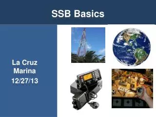
A 60 meter SSB transmitter Nick Kennedy, WA5BDU OzarkCon, Joplin MO April 29, 2006
Introductory inspirational quotes Thoughts from JF1OZL’s homebrew web page: Some of the successful projects was born from the failed idea. We have the proverb ," Failure is the mother of the success." in Japan. You may write your notebook not to record your successful projects, but raise your new idea. Why I make my rigs by myself: Sometime I receive the question " Why do you make your rigs by yourself?". I can not answer the question. The man making such question thinks as follows. It cost only about $500 to buy cheap rigs. It cost about $1000 to buy some test equipment. I can understand what he says. But I want to say as follows. The purpose of Amateur radio is to spend money and to spend times. It makes no economical profit to the station manager. To make high tower costs very high . To make shack on the mountain costs high . To go to expedition cost very high. And also to make my original rig costs very high. It is the way of Amateur life. From Frank Harris’ on-line book: Crystal Sets to Sideband, Chapter 15: The Nobel Prize for Sideband: Getting on 60 meters SSB - don't bother! Before the 60 meter SSB frequency became available to American hams on July 4th 2003, I thought it would be fun to get on the air before the commercial gear was on the market. I naively thought that homebrewers would own the frequency for at least a little while. What I didn't know was that some of the newest transceivers can be reprogrammed to operate on any HF frequency just by pushing some buttons. Anyway, The band was instantly clogged with commercial transceivers.
Verbal Block Diagram • Speech amp, then audio BW shaping • Carrier oscillator (VXO crystal oscillator) • Balanced modulator MC1496; 9MHz DSB out • Crystal filter produces SSB • DDS for local oscillator “VFO” (PIC control) • Transmit mixer NE602, moves to 5.3 MHz • Several stages of linear amplification • We’re done, take a break!
NE5532 Audio BPF MC1496 DBM 5-p crystal filter NE602 transmit mixer LM387 40dB speech amp & clipper electret microphone 9 MHz carrier osc DDS Controller 101101 PIC16F84A AD9850 DDS Class A TN2219A 20 dB to +9dBm Class A RCA4013 15 dB to 100mW out Class AB 2N3866 push-pull to 1 watt Class AB 2SC2075 push-pull to 5 watts 5 element LPF; Fco = 5.75 MHz 6 MHz LPF 60 meter SSB transmitter block diagram
Microphone preamp/limiter • Two stage LM387 with 1st stage clipping • Gain of 10 per stage for 40 dB total • Balanced modulator needs about 1Vrms • Gain of 1st stage set to clip at ~maximum • Single supply design leads to some complexity & limits flexibility. • Bias voltage provided at input for electret type microphone. Also RF filter at input.
Audio bandwidth filtering • NE5532 LPF and HPF stages in series • Voice BW filtering more difficult than CW; hard to achieve in a single stage • Gain of 1; target BW 500 to 2200 Hz • Two pole Salen-Key 40dB/decade roll-off; (TI “ Single Supply Op-Amp Circuit Collection”) • Attempted to use quality film or poly capacitors in audio signal train
9.000 MHz Carrier Oscillator • Colpitts with additional amplifier stage • Uses a crystal from the filter set • Series L & C may require juggling to hit the required frequency • Adjust ~500 Hz beyond edge of filter BW • MC1496 needs about 160 mV rms drive • Reliable circuit; requires minimal fuss to work. Ref. EMRFD fig 6.103
Balanced modulator • MC1496 similar to NE602; Gilbert cell • DC bias: R1, R2, R3 are a voltage divider to bias pins 6/12 2V above 8/10; 8/10 2.7V above 1/4; 1/4 2.7V above 5 • R7 sets I5 current into pin 5 at (12-0.7)/(6k8+500) or 1.6mA • I5 * R8 = 1.6 volts, sets peak allowable audio level at 1.6 volts, or 1.12 Vrms.
R8 sets gain; 1k is typical per data sheet • R9 sets current source differential output Z at 2k2 and T1 matches 2k2 to the 200Ω crystal filter. • RF input for best sideband suppression 160 mV rms @ 10MHz per datasheet figure 22, in same ballpark with EMRFD value of 300 to 500 Vp-p. • R4 & R5 isolate RF & AF inputs from bias nodes at AC ground.
MC1496 Schematic NE602 (SA612) equivalent schematic Comparison of MC1496 & NE602
5-pole 9 MHz crystal filter • Passes desired sideband of DSB output from balanced modulator • Voice bandwidth is a greater challenge due to parallel resonance in crystals; compensated with parallel inductors. • XLAD, AADE & other software available • Actual BW usually wider than calculated • 200 ohm Z for better capacitor values
Narrow view of inductance compensated filter BW (LTSpice simulation)
Wide bandwidth look at inductance compensated filter (LTSpice simulation)
Narrow look at filter without compensation (note LSB shape) (LTSpice simulation)
Wide view of filter without compensation-- good wideband attenuation (LTSpice simulation)
DDS “VFO” • Above or below 9 MHz to produce 5 MHz? • Above allows feedthru out of mixer to be filtered by LPF. But it inverts the sideband. • Output of NJQRP AD9850 is adequate for NE602 requirements with margin. • Discrete channels of 60 meter band simplifies user interface to 1 button & annunciation. • PIC16F84 is more than up to the task.
Transmit mixer: NE602 • 6 VDC supply • R-pad matches 200 ohm filter to 1k5 input & gives 15 dB attn of 9 MHz SSB to pin 1 • From DDS, resistive divider drops DDS output to about 630mVp-p @ pin 6 • Transformer output for balanced 3,000 output (pin 4,5) to 200 filter • 4-element LPF at output
Two class-A amplifier stages • Post-mixer amplification needed to get from -11 dBm to +20 dBm power level • Class-A used where possible for lowest distortion, plus easy & predictable • TN2219A first stage & RCA4013 second • EMRFD figure 2.57 primary resource; added 4:1 xfmr at input to match 200 • Standing current 20mA 1st; 40mA 2nd.
1-watt push-pull driver • Class AB push-pull 2N3866 • Temperature compensated bias control • Classic design with these wrinkles: • Emitter degeneration, AC & DC • No shunt or xfmr feedback • Input swamping resistors AC coupled • Gain over 20dB; added some input attenuation.
Push-pull 10 w final amp / filter • Classic push-pull topology • Temperature compensated amplified bias • Balun binocular cores, brass tube primary winding on output. • Emitter degeneration; no shunt feedback • 5-element output filter
Completed transmitter --- but where is it? In ten separate pieces ; nine boxes