Download
1 / 7
70 likes | 78 Vues
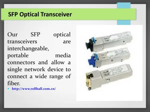
Small Form Factor Pluggable (SFP ) transceivers are compatible with SFF-8431,SFF-8432 and support<br>10G Ethernet ER and 10G Fibre Channel . It is designed for use in 10G-Gigabit multi-rate links up to 40km<br>of G.652 . Digital diagnostics functions are available via a 2-wire serial interface as specified in SFF-8472

E N D
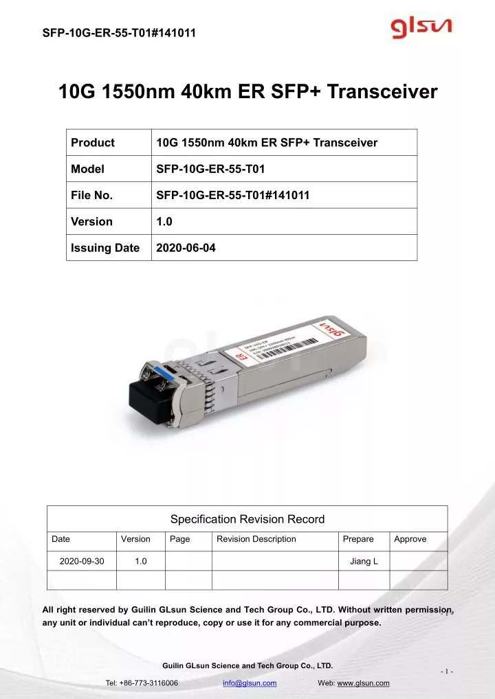
SFP-10G-ER-55-T01#141011 10G 1550nm 40km ER SFP+ Transceiver Product 10G 1550nm 40km ER SFP+ Transceiver Model SFP-10G-ER-55-T01 File No. SFP-10G-ER-55-T01#141011 Version 1.0 Issuing Date 2020-06-04 Specification Revision Record Date Version Page Revision Description Prepare Approve 2020-09-30 1.0 Jiang L All right reserved by Guilin GLsun Science and Tech Group Co., LTD. Without written permission, any unit or individual can’t reproduce, copy or use it for any commercial purpose. - 1 - Guilin GLsun Science and Tech Group Co., LTD. - 1 - Tel: +86-773-3116006 info@glsun.com Web: www.glsun.com
SFP-10G-ER-55-T01#141011 Product Description Small Form Factor Pluggable (SFP+) transceivers are compatible with SFF-8431,SFF-8432 and support 10G Ethernet ER and 10G Fibre Channel . It is designed for use in 10G-Gigabit multi-rate links up to 40km of G.652 . Digital diagnostics functions are available via a 2-wire serial interface as specified in SFF-8472. Product Feature Supports 9.95 to 11.3Gb/s Duplex LC connector Hot-pluggable SFP footprint Cooled 1550nm EML laser RoHS compliant and Lead Free 40km link length Metal enclosure for lower EMI Built-in dual CDR Power dissipation <2.0W (0~70℃),<2.3W(0~85℃) , <2.3W(-40~85℃) Commercial and industrial operating temperature optional SFP MSA SFF-8472 SFF-8431 SFF-8432 IEEE 802.3 Compliant Regulatory Compliance ESD to the Electrical PINs: compatible with MIL-STD-883 Method 3015 ESD to the Duplex LC Receptacle: compatible with EN 61000-4-2 Immunity compatible with EN 61000-4-3 EMI compatible with FCC Part 15 Class B Laser Eye Safety compatible with FDA 21CFR 1040.10 and 1040.11 IEC 60950, IEC60825-1,2 RoHS compliant with RoHS 2.0(2015/863/EU)-amending. General Specifications Parameter Symbol Min Typ Max Unit Ref. Maximum Supply Voltage Vcc V -0.5 +4.0 Storage Temperature TS °C -40 +85 Operating Humidity RH % 0 85 Power Supply Voltage Vcc3 3.13 3.30 3.47 V Icc Icc Icc Tc Te TI 600 700 700 +70 85 85 mA mA mA °C °C °C 1 Power Supply Current Extend 2 0 0 1 2 Case Operating Temperature -40 Guilin GLsun Science and Tech Group Co., LTD. - 2 - Tel: +86-773-3116006 info@glsun.com Web: www.glsun.com
SFP-10G-ER-55-T01#141011 Bit Rate BR 9.95 11.3 Gbps 9/125um G.652 SMF Lmax 40 Km Notes: 1. For commercial class product. 2. For industrial class product. Electrical Characteristics Parameter Symbol Min Typ Max Unit Ref. Transmitter Input differential impedance Rin 80 100 120 Ω 1 Single ended data input swing Vin, pp 120 850 mV TX Disable-High Vcc –0.8 Vcc V TX Disable-Low Vee Vee+ 0.8 V TX Fault-High Vcc-0.8 Vcc V TX Fault-Low Vee Vee+0.8 V Receiver Single ended data output swing Vout, pp 300 850 mV 2 Data output rise time Tr 28 ps 3 Data output fall time Tf 28 ps 3 LOS-High Vcc– 0.8 Vcc V LOS-Low Vee Vee+0.8 V Notes: 1. AC coupled. 2. Into 100 ohm differential termination. 3. 20–80 % Optical Characteristics Parameter Symbol Min Typ Max Unit Ref. Transmitter Output Opt. Power PO -3 4 dBm Optical Wavelength Λ 1530 1565 nm Side-Mode Suppression Ratio SMSR 30 RMS Spectral Width(-20dB) Δλ 1 nm Guilin GLsun Science and Tech Group Co., LTD. - 3 - Tel: +86-773-3116006 info@glsun.com Web: www.glsun.com
SFP-10G-ER-55-T01#141011 Relative Intensity Noise RIN -128 dB/Hz Path penalty at 800ps/nm@9.95Gb/s TDP 2 dB Optical Extinction Ratio ER 8.2 dB Receiver RX Sensitivity @10.3Gb/s SENS -15.8 dBm 1,2 Receiver Overload -1 dBm Optical Center Wavelength λC 1260 1600 nm LOS De-Assert LOSD -20 dBm LOS Assert LOSA -34 dBm LOS Hysteresis 0.5 dB Notes: 1.Measured with conformance signals defined in FC-PI-2 Rev. 10.0 specifications. 2.Measured with PRBS 231-1 at 10-12BER. Pin Descriptions Pin Symbol Name Ref. 1 VeeT Transmitter Ground (Common with Receiver Ground) 1 2 TX Fault Transmitter Fault. LVTTL-O 2 3 TX Disable Transmitter Disable. Laser output disabled on high or open. LVTTL-I 3 2-Wire Serial Interface Data Line (Same as MOD-DEF2 in INF-8074i). LVTTL-I/O 2-Wire Serial Interface Data Line (Same as MOD-DEF2 in INF-8074i). LVTTL-I 4 SDA 2 5 SCL 2 6 Mod_ ABS Module Absent, Connect to VeeT or VeeR in Module. 2 7 RS0 Rate Select 0, optionally controls SFP+ module receiver LVTTL-I 4 Loss of Signal indication. Logic 0 indicates normal operation. LVTTL-O 8 LOS 5 9 RS1 Rate Select 1, optionally controls SFP+ module transmitter. LVTTL-I 4 10 VeeR Receiver Ground (Common with Transmitter Ground) 1 11 VeeR Receiver Ground (Common with Transmitter Ground) 1 RD- 12 Receiver Inverted DATA out. AC Coupled. CML-O 13 RD+ Receiver Non-inverted DATA out. AC Coupled. CML-O 14 VeeR Receiver Ground (Common with Transmitter Ground) 1 15 VccR Receiver Power Supply 6 Guilin GLsun Science and Tech Group Co., LTD. - 4 - Tel: +86-773-3116006 info@glsun.com Web: www.glsun.com
SFP-10G-ER-55-T01#141011 16 VccT Transmitter Power Supply 6 17 VeeT Transmitter Ground (Common with Receiver Ground) 1 18 TD+ Transmitter Non-Inverted DATA in. AC Coupled. CML- I 19 TD- Transmitter Inverted DATA in. AC Coupled. CML- I 20 VeeT Transmitter Ground (Common with Receiver Ground) 1 Note 1. Circuit ground is internally isolated from chassis ground. 2. TX Fault is an open collector/drain output .Which should be pulled up with a 4.7K –10K Ohms resistor on the host board if intended for use. Pull up voltage should be between 2.0V to Vcc+0.3V.A high output indicates a transmitter fault caused by either the tx bias current or the tx output power exceeding the preset alarm thresholds. A low output indicates normal operation .In the low state, the output is pulled to <0.8V. 3. Laser output disabled on TX Disable >2.0V or open, enabled on TX Disable<0.8V. 4. Internally pulled down per SFF-8431 Rev4.1. 5. LOS is open collector output. Should be pulled up with 4.7k – 10kohms on host board to a voltage between 2.0V and 3.6V. Logic 0 indicates normal operation; logic 1 indicates loss of signal. 6. Internally connected Pin-out of Connector Block on Host Board Guilin GLsun Science and Tech Group Co., LTD. - 5 - Tel: +86-773-3116006 info@glsun.com Web: www.glsun.com
SFP-10G-ER-55-T01#141011 Recommend Circuit Schematic Mechanical Specifications Small Form Factor Pluggable (SFP+) transceivers are compatible with the dimensions defined by the SFP Multi-Sourcing Agreement (MSA) . Guilin GLsun Science and Tech Group Co., LTD. - 6 - Tel: +86-773-3116006 info@glsun.com Web: www.glsun.com
SFP-10G-ER-55-T01#141011 EEPROM Information EEPROM memory map specific data field description is as below: Digital Diagnostic Monitoring Interface Five transceiver parameter values are monitored. The following table defines the monitored parameter’s accuracy Parameter Range Accuracy Calibration 0 to +70°C (C) 0 to +85°C (E) -40 to +85°C (I) Temperature ±3°C Internal Voltage 2.97 to 3.63V ±3% Internal Bias Current 0 to 100mA ±10% Internal TX Power -1 to 4 dBm ±3dB Internal RX Power -16 to -1dBm ±3dB Internal Ordering Information Part Number Operating Case temperature DDMI SFP-10G-ER-55-T01 Commercial (0~70℃) Yes Guilin GLsun Science and Tech Group Co., LTD. - 7 - Tel: +86-773-3116006 info@glsun.com Web: www.glsun.com