pond heater for koi
20 likes | 43 Vues
ThermaKoi <br>Instructions <br>1. Hook up plumbing to flow into the inlet and back to the holding vessel via the outlet. <br>2. Plug unit into a dedicated 20 amp outlet (115 volt) on the 1.5 KW model. On the 6 KW, 11 KW and 18 KW <br>units these must be hard wired (230 volt) into place according to local codes. Please consult an electrician <br>for local codes and proper electrical hook up. <br>3. Make sure unit is installed level horizontally. <br>4. On initial run before starting, rotate temp control knob to off (standard non-digital model). Start water flowu0002ing before rotating temp control knob. Unit is designe

pond heater for koi
E N D
Presentation Transcript
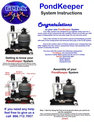
PondKeeper System Instructions Congratulations Congratulations on your new PondKeeper System Your filter system was designed to go together easily even for a novice. Each of the components was carefully chosen to provide you with years of dependable service and clear water for you and your pond. Take a few minutes to look at this manual and familiarize yourself with each of the components and what part they play in the PLUS system. Due to the custom nature of these systems your components may differ slightly from the various components shown, but assembly of the system is basically the same. You have with this system the following components: PondKeeper bio-mechanical filter Dynamo 2 speed Water pump (can be one of a variety) ZapTek2 Ultraviolet light Plumbing parts Media Agitator Equipment pad Getting to know your PondKeeper System Taking a few minutes to get to know the different compo- nents of your PondKeeper System will assure that you are using it to it’s maximum potential. Assembly of your PondKeeper System Multiport Backwash valve Media Agitator Filter Unions Water pump (Various) 2 speed shown PondKeeper Filter ZapTek2 Stainless Steel UV Water Drain Equipment Pad ZapTek UV Sight glass If you need any help feel free to give us a call 866.712.7007 Step 1: Start by laying the Pad on level ground where you want to lo- cate the equipment. Note: Locating the equipment as close as possible or below the surface grade(water level) of the pond will result in best results. Distance from the pond is not as critical as the distance above the surface grade. (over)
PondKeeper System Assembly PondKeeper System Assembly Step 2 : Set the filter, pump and UV on the pad as shown. Place media Agitator on Check valve. Do not glue Agitator to pipe. Use a set screw through the pipe and agitator throat if needed to hold it. Connect like number to like number by tightening the un- ions together by hand. Step 3: Attach the ZapTek UV to the filter outlet as shown. Attach pipe to pump and inlet of filter. Hand tighten only the unions. Make sure the gaskets are in the unions at the connections. PondKeeper System Assembly PondKeeper Backwash and Winterizing Instructions Waste line Slide Valve Inlet (water in from pond) Backwash the filter at least once per week to keep the filter in top run- ning condition. Do not allow filter to run for extended periods of time before doing a backwash or it will be harder to clean the filter resulting in less than perfect water quality. 1. Turn pump off. Turn UV off, if equipped. Open Slide Valve(pull out- ward) Move handle to “Backwash”. Turn Agitator on using bursts of 20 seconds on / 5 seconds off and repeat a few times until media is completely broken apart. Turn Agitator off. Close Slide Valve(Push inward) Turn pump on “HIGH” and run until water is clear in sight glass. Turn pump off. 2. Move handle to “Rinse”. Turn pump on “HIGH” and run until water is clear in sight glass. Turn pump off. 3. Move handle to “Filter” and Turn pump on. Turn UV on, if equipped. Never run UV without pump being on. Other settings on your dial are the following: Waste: Bypasses the filter and sends water to waste. Recirculate: Bypasses the filter and sends water back to the pond. Closed: keeps water from going through filter. Winterizing Drain water from the filter and pump to make sure system does not freeze and bust. Freezing is not covered by your warranty. Return Line Going back to pond. Step 4: Your system should now look like this. Now it’s time to hook the system up to your pipe work of your pond. For maximum flow 2” pipe is recommended. 1. Hook up pump inlet to receive water coming from the pond. We recommend a swing check valve on this line, preferably below sur- face grade. Just glue the line into the union on the front of the pump using pvc glue and cleaner or primer. 2. Run the “Return” pipe back to the pond, such as a waterfall. 3. Hook up your “Waste” line to direct the dirty water on backwash out to waste. Pump control speed switch is lo- cated on the back of the pump. It has 2 speeds(low and high) and OFF setting. OFF is the middle setting.