Download
1 / 22
0 likes | 8 Vues
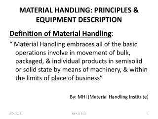
Globe Overseas Pvt. Ltd. Founded in 1995, u201cGlobeu201d is an acknowledged leader of Indiau2019s Material Handling Industry. Dedicated to providing innovative solutions that redefine efficiency and safety in various industrial operations. With a commitment to excellence, we specialize in the design, manufacturing, and distribution of high-quality material handling equipment, catering to diverse sectors across the globe. https://liftingmachines.in/

E N D
Our Certificates Our Facilities Our Clientele
We Build Trust Chain Pulley Block Classic Series TO BE INNOVATIVE Through steady research & development we have achieved international product design and so we are continuously innovating our product range. TO BE CUSTOMER ORIENTED Experience of more than 25 years of our professional engineers is put into each product, in response to our customer's refined needs. FAST DELIVERY SCHEDULE Globe is equipped with vast efficient production line which is handled by skillful workers. SAFETY & HIGH STRENGTH All equipments are designed as per IS safety standards as well as long life robust structural design. EASY MAINTAINANCE During the design of the equipments, our R&D team always take care of the ease of maintenance & our effiicient maintenance team makes it more competitive.
Salient Features Confirming to IS 3832 : 2005 Model - CL • Gr. 80 alloy steel load chain • Light weight & compact • Low headroom • Minimum hand effort. • Sturdy • Smooth running & good appearence A B A B LOAD CHAIN SPROCKET Steel recommended as per IS 3832, ultra fine quality fully pocketed cast steel & precisely machined to suit calibrated load chain & roller bearing for free rotation, reducing effort for lifting. Improved life cycle and smooth running. HOOK Heavy duty steel forged compact hook for top& bottom hook assembly with safety latch, capable to withstand shock loads manufactured as per IS 15560-2005. H H SAFE BRAKING ARRANGEMENT Self-actuating screw disc type mechanical braking arrangement with non-asbestos based brake disc provides long lasting and high performance. C C D D GEAR SET Highly efficient, compact and hard wearing gears manufactured from alloy steel, precisely machined and processed. TECHNICAL SPECIFICATION TRIPLE PROTECTION COVER Heavy duty steel coated cover protects from atmospheric conditions, external shocks and improves life of complete chain block. CHAIN PULLEY BLOCKS - CLASSIC SERIES Model CL1S CL2S CL2D CL3S CL3D CL3F Capacity Ton 1 2 3 3 5 10 CHAIN GUIDE ROLLER Standard lifting height Mtr 3 3 3 3 3 3 Double chain guide rollers ensures accurate alignments & smooth movement of load chain. Running test load Ton 1.25 2.5 3.75 3.75 6.25 12.5 Headroom H mm 410 480 600 580 770 950 No. of fall - 1 1 2 1 2 4 Chain dia & Pitch mm 6.3X19 8X24 8X24 10X30 10X30 10X30 RATCHET & PAWL ARRANGEMENT Hand effort in (kg) Kg 25 30 37 37 36 39 2 Nos. spring loaded heavy duty heat treated pawl enhances the performance and improves safety in all positions. A mm 172 220 232 234 292 400 B Dimension mm 155 178 178 190 190 192 C mm 27 30 38 38 48 62 D mm 36 38 50 50 63 82 BEARINGS Packing measurement (LXWXH) Cm 27x19x17 30x22x18 45x26x23 45X44X36 47X44X36 53X51X47 High quality steel housing ball and needle bearings improves efficiency. Net Weight Kg 13.5 21 29 33.5 39 78 Extra weight per meter of extra lift Kg 1.6 2.2 3.0 3.6 5.2 9.6 Note :- Due to continuous development and improvement specification listed above may be changed without notice.
Chain Pulley Block Robo Series Confirming to IS 3832 : 2005 Model - RB TECHNICAL SPECIFICATION CHAIN PULLEY BLOCK – ROBO SERIES Model RB1 RB1 RB1 RB2 RB2 RB2 RB2 RB3 RB3 Capacity Ton 1 2 3 5 7.5 10 15 20 25 Standard Lifting Height Mtr 3 3 3 3 3 3 3 3 3 Headroom H mm 495 515 720 850 960 980 1250 1300 1450 Load Chain Ø & Pitch mm 8x24 8x24 8x24 10X30 10X30 10X30 10X30 12X33.5 12X33.5 No. of Falls - 1 1 2 2 3 4 5 6 6 kg Hand Effort in 35 40 45 40 40 52 80 85 95 mm Dimension A 255 255 290 345 415 425 600 1220 - mm B 185 185 185 220 220 220 - - - - Velocity Ratio App. 50.5 50.5 102 280 216 298 430 592 740 kg 26 27 35 61 82 106 176 266 280 Net Weight kg 2.9 2.9 4.3 5.7 8.5 10.6 20.1 27.8 27.8 Extra Weight/ Mtr. Lift Note :- Due to continuous development and improvement specification listed above may be changed without notice.
Salient Features • Once installed works years together • Longer life • Easy to handle • Negligible maintenance cost • Low cost • Quick dependable lifting 9 IMPORTANT FEATURES OF GLOBE “ROBO” SERIES CHAIN BLOCKS. LIFTING HOOKS Heavy duty steel forged hooks, capable to withstand shock loads. Free to swivel & rotate, design as per IS 15560. BASE FRAME Robust & long life designed structure, which ensures the safety on safe loads and overloaded conditions. Moreover it is more sustainable in hazardous conditions also. LOAD CHAIN SPROCKET Steel casted & hardened, designed to adjust precisely of load chain which ensure increased and long life of chain & Load chain Sprockets resulting minimum wear of parts. GEARS Gear Box is the heart of Chain blocks, hence material selection, all manufacturing processes of gears are done very precisely. All gears and pinions are Case hardened as per IS Standards. BRAKING ARRANGEMENT Self actuating screw disc type ensures full safety. Steel forged pawl, hardened ratchet Gears HAND CHAIN WHEEL Heavy duty & large diameter of hand wheel gives smooth and effortless lifting. LOAD CHAIN Grade 80, alloy steel load chain as per IS Standards electrically resistance welded, heat treated, tested & Calibrated. BRAKE DISC Asbestos free long lasting, minimum wear & more griping ability LOAD CHAIN GUIDE It ensures to facilitate smooth & twist free monument of load chain.
Confirming to IS - 807 & 3177 Monorail Travelling Trolley • GEARED TYPE E C F A Geared Type B D • PUSH PULL TYPE C F A B D TECHNICAL SPECIFICATION MONORAIL TRAVELLING TROLLEY GEARED TYPE Push Pull Type PUSH PULL TYPE Model GBT1 GBT2 GBT3 GBT5 GBT10 PPT1 PPT2 PPT3 PPT5 Capacity 1 2 3 5 10 1 2 3 5 Ton Standard lifting height 3 3 3 3 3 - - - - Mtr I-Beam recommended 65-125 75-140 100-150 125-180 140-210 65-125 75-140 100-150 125-180 mm Dimension A 24 27 31 30 28 24 27 31 30 mm Dimension B 115 132 166 192 264 115 132 166 192 mm Dimension C 60 80 104 130 147 60 80 104 130 mm Dimension D 227 252 295 345 200 227 252 200 295 mm Dimension E 258 284 308 350 407 - - - - mm Dimension F 220 250 292 321 504 220 250 292 321 mm Packing measurement (LXWXH) 28X25X23 30X28X25 32X32X28 36X35X30 36X35X30 53X43X41 25X23X17 29X25X20 32X30X30 cm Net weight with 3m lift 13 19 27 39 94 9 14 22 33 kg Extra weight per meter of extra lift 0.9 0.9 0.9 0.9 0.9 - - - - kg Hand Chain (фXpitch) 5X22.5 5X22.5 5X22.5 5X22.5 5X22.5 - - - - mm Radius of curvature 2000 2000 1500 1500 1500 2000 2000 1500 1500 mm Note :- Due to continuous development and improvement specification listed above may be changed without notice.
Confirming to IS 3938 Model - M Series Electric Wire Rope Hoist FFL TECHNICAL SPECIFICATION ELECTRIC WIRE ROPE HOIST WITH ELECTRIC TROLLEY GWRH M4-204 GWRH M0-62 GWRH M1-82 GWRH M1-84 GWRH M2-102 GWRH M2-104 GWRH M2-124 GWRH M3-124 GWRH M3-144 GWRH M4-164 Model Rated Load 15 0.5 Ton 1 2 2 3 5 5 7.5 10 6 Lift 5 Mtr 6 6 6 6 6 6 6 6 3 6 mpm 6 3 4 3 3 3 3 3 Hoisting speed 15 1 H.P 2 2 3 3 5 5 7.5 10 Hoisting motor 15 15 mpm 15 15 15 15 15 15 15 15 Traversing speed 1.5 0.25 H.P 0.5 0.5 0.5 0.5 1 1 1 1 Traversing Motor 40 % CDF, 150 Starts/Hr, 50 Hz, 415V, 3 Phase, AC, Squirrel cage Induction Motor, IE2. Motor Specifications No. of falls 4 - 2 2 4 2 4 4 4 4 4 Rope Diameter 20 mm 6 8 8 10 10 12 12 14 16 Rope Construction 6 x 36 / 37, Fibre Core (FMC) /1770 N/MM Sq., Ungalvanised, Breaking Strength - 40KN. Approx. Weight 1400 160 kg 216 240 400 460 540 800 900 1200 - - - - A 385 mm 425 425 480 480 480 - - - - B 115 mm 125 125 150 150 150 - C 200 mm 290 300 360 360 360 415 415 500 - D 700 mm 750 920 950 1000 1100 1200 1250 1400 - E 300 mm 380 380 460 460 460 585 585 655 Approx. Dimensions - F 300 mm 380 380 400 400 400 580 580 580 - G 720 mm 830 1050 1040 1040 1040 1090 1090 1200 - H 265 mm 260 260 375 375 375 280 280 315 - I 6000 mm 6000 6000 6000 6000 6000 6000 6000 6000 - J 390 mm 530 530 720 720 720 830 830 1000 - - - - K 600 mm 740 750 840 840 840 Recommended ISMB Sizes 150 x 75 to 200 x 100 200 x 100 to 350 x 140 250 x 125 to 450 x 150 300 x 140 to 600 x210 mm Note :- Due to continuous development and improvement specification listed above may be changed without notice.
Salient Features DESIGN “Globe” Electric Wire Rope Hoists are designed as per IS 3938 - 1983 (R2012) and are suitable for Medium & Heavy duty applications. We also do customizations in hoists as per Customer Requirements. CONSTRUCTION “GLOBE” hoist have a unique modular construction which makes them an ideal choice since each sub assembly is easily accessible individually, thus reducing the time and cost involved in the maintenance. STRUCTURE Years of Experience for different applications enabled “Globe” to produce heavy duty / robust structure which ensures long life & safety of the user, material & machinery. ROPE DRUM Rope drums are fabricated with seamless tubes having flanges at both ends. Each drum is precisely machined and grooved suitably for specified wire ropes. Ropes guiding arrangements ensures & protect overlapping of wire rope & winds full length of rope in one layer. GEAR BOX Totally enclosed, immersed oil bath lubricated Gearbox, fitted with heavy duty precision cut helical Gears and Pinions with alloy Steel material. HOOK Conforming to IS: 15560 Free to rotate & swivel. BRAKE Instant action ‘fail to safe’ Electromagnetic DC disc type, ensures maximum safety and reliability in operation. LIMIT SWITCH Snap action limits switch to prevent over hoisting and over lowering is provided for maximum safety. CONTROL From push button pendent station supported with steel wire rope, operating at 110 volt from ground level.
Confirming to IS - 6547 Model 'MC' Series Electric Chain Hoist TECHNICAL SPECIFICATION ELECTRIC CHAIN HOIST GCH MC1-81 GCH MC1-82 GCH MC2-102 GCH MC2-102 MODEL CAPACITY 1T Ton 2T 3T 5T HEIGHT OF LIFT 3 3 3 Mtr 3 3 3 MAIN HOISTING SPEED 6 mpm 3 3 5 MAIN HOISTING MOTOR 2 H.P 2 2 / 10 2 / 10 LOAD CHAIN / FALL 1 / 8 mm 2 / 8 15 15 CROSS TRAVEL SPEED mpm 15 15 0.5 1 CROSS TRAVEL MOTOR 0.5 H.P 0.5 302 357 Width 'A' 270 mm 270 681 741 Overall 'B' 607 mm 607 910 1070 Head Room 'H' 735 mm 800 68 103 Dimension 'F' 99 mm 68 235 256 Dimension 'G' 170 mm 203 316 330 Dimension 'J' 294 mm 293 365 411 Dimension 'K' 313 mm 313 Note :- Due to continuous development and improvement specification listed above may be changed without notice.
Salient Features DESIGN “GLOBE” Electric Chain Hoist are designed as per IS: 6547 and are suitable for Medium & Heavy duty applications. CONSTRUCTION “GLOBE” Hoist have a unique modular construction which makes them an ideal choice since each sub assembly is easily accessible individually, thus reducing the time and cost involved in the maintenance. FRAME The Frame is of sturdy design, fabricated from tested steel plates and is welded/bolted type. GEAR BOX Totally enclosed, gear box with gears made from EN-9/EN- 24, steel and teethed on precision hobbing machines, hardened & tempered. The gears are lubricated with high viscosity grease and need no further lubrication. ELECTRIC MOTORS 3 PH. 440 Volt, A. C. 50 cycles, Squirrel cage Induction motors normally of BBL/ ABB/CGL make is used. LOAD CHAIN Confirming to IS : 6216-1971, Grade 80, tested, calibrated and duly heat treated. BRAKE Instant action ‘Fail to Safe’ Electro Magnetic Disc brakes are incorporated to ensure maximum safety and reliability in operation. LIMIT SWITCH Snap Action limits switches are used to prevent over hoisting and over lowering. CONTROL PANNEL Totally enclosed, dust and moisture proof panel housing with components of standard makes like ‘SIEMENS/L&T, BCH’ telemechanique etc., provided control at low voltage for safety of operator. HOOKS Steel Forge confirming to IS : 15560-2005. Free to rotate & swivel. TEST Each Hoist is tested to 25% Overload with confirmation to IS : 6547-1971.
Electric Winch Confirming to IS- 9507-1979 (R2006) TECHNICAL SPECIFICATION ELECTRIC WINCH Winding Capacity / No. Of Layer Rope Speed Mtr./Min. Rope Dia (Mm) Suggested Capacity In Ton Gear Box Motor H.P 1 TON WORM 6 90 Mtr./ 4LYR 2 10 1 TON WORM 6 140 Mtr./ 4LYR 3 10 1 TON WORM 9 90 Mtr./ 4LYR 3 10 1 TON WORM 9 140 Mtr./ 4LYR 3 10 1 TON WORM 12 90 Mtr./ 4LYR 5 10 1 TON WORM 12 140 Mtr./ 4LYR 5 10 2 TON WORM 6 90 Mtr./ 4LYR 5 12 2 TON WORM 6 140 Mtr./ 4LYR 5 12 2 TON WORM 9 90 Mtr./ 4LYR 7.5 12 2 TON WORM 9 140 Mtr./ 4LYR 7.5 12 2 TON WORM 12 90 Mtr./ 4LYR 10 12 2 TON WORM 12 140 Mtr./ 4LYR 10 12 3 TON WORM 6 100 Mtr./ 4LYR 7.5 16 3 TON WORM 6 200 Mtr./ 4LYR 7.5 16 3 TON WORM 9 100 Mtr./ 4LYR 10 16 3 TON WORM 9 200 Mtr./ 4LYR 10 16 3 TON WORM 12 100 Mtr./ 4LYR 12.5 16 3 TON WORM 12 200 Mtr./ 4LYR 12.5 16 5 TON WORM 6 100 Mtr./ 4LYR 10 22 5 TON WORM 6 100 Mtr./ 4LYR 10 22 5 TON WORM 7.5 200 Mtr./ 4LYR 12.5 22 5 TON WORM 7.5 200 Mtr./ 4LYR 12.5 22 5 TON WORM 9 100 Mtr./ 4LYR 15 22 5 TON WORM 9 200 Mtr./ 4LYR 15 22 7.5 TON HELICAL 5 100 Mtr./5LYR 12.5 22 7.5 TON HELICAL 5 200 Mtr./5LYR 12.5 22 10 TON HELICAL 4.5 100 Mtr./5LYR 15 30 10 TON HELICAL 4.5 200 Mtr./5LYR 15 30 15 TON HELICAL 4.5 100 Mtr./5LYR 20 40 15 TON HELICAL 4.5 200 Mtr./5LYR 20 40 Note :- Due to continuous development and improvement specification listed above may be changed without notice.
Salient Features DESIGN “Globe” Electric Winch Machines are designed as per IS: 9507-1979 (Reconfirmed 2006) and are suitable for Medium & Heavy duty applications. CONSTRUCTION “GLOBE” Winches have a unique modular construction which makes them an ideal choice since each sub assembly is easily accessible individually, thus reducing the time and cost involved in the maintenance. FRAME The Structural Base Frame is of sturdy design, fabricated from tested steel plates and is welded/bolted type. GEAR BOX Totally enclosed Worm/ Helical Type with suitable open Reductions as per speed requirement. All gear are Precision hob machined & are lubricated with high Quality Gear Oil. ELECTRIC MOTORS 3 Phase, 415 Volt, 50Hz , AC , S1/S4 Duty, Squirrel cage induction motors. Make- BBL/ CGL/ ABB are used. BRAKE Electro magnetic Disc / Shoe or Electro Hydraulic thrustor shoe type Brake as provided as per required Torque. LIMIT SWITCHES Rotary Geared type limit switches to Prevent over travel in both Directions reverse & forward, motion. CONTROL PANEL Totally enclosed, dust & moisture proof Panel Housing, IP 55 Protected, housed with Heavy duty Contactors & Safety Components for Safe operation. Make of Components – Schneider electric / ABB / L&T / Siemens SAFETY GUARDS All open Reduction Gear are covered with Safety Guard to avoid any kind of Mishap, Specially for Machine operator. Test : All machines are tested to 25% over load as per relevant IS Standard. OPTIONAL ACCESSORIES • Wire Rope • Eye Hook • VFD Panel ADDITIONAL FEATURES / ADVANTAGES • Multifunctional and can be manufactured at higher capacities also. • Long Distance pulling can be done. • High-speed winches can reduce travel time. • Low Maintenance • Spares are easily available all around. • Dual Braking makes the operation safer. • Winches can be designed with helical and worm Gear boxes. • Multiple Layering of rope can be done with rope winch guiding arrangement.
Crab Winch Confirming to IS - 5112 Salient Features APPLICATION “GLOBE” manual Crab Winches are used for Pulling Heavy loads, Lifting Application, Erection of pillars and poles, Tensioning of electric Power Line Towers, Dam Gate Lifting, cable pulling etc. STRUCTURE Complete structure is fabricated from Tested steel as per IS 2062. REDUCTION GEARS 2 & 3 Stage Gear train reduces hand effort for heavy loads as per capacity, which makes the machine more users friendly. Heavy Duty Fabricated, Precisely turned and Hob cut gears are used mounted on Ball bearings. DUAL SPEED This is a special feature of our winch machine, all standard machines have dual speed for free and loaded conditions which help user to minimize working time and improves efficiency. ROPE DRUM Fabricated Plane Drums having flanges at both ends and are designed to withstand the compressive stresses caused by the wound of rope when the drum is wound. Drum diameter and lengths are designed as per Rope Size & winding capacity/standard in multi layers. DUAL BRAKING Each winch is provided with twin braking arrangement which makes our winches fail safe. 1st Brake – Ratchet & Pawl arrangement 2nd Brake – manual Drum shoe brake Each brake is suitable to sustain full load capacity. OPERATING HANDLES Heavy duty with suitable required length of operating handles is provided on both sides of driving shaft which helps to distribute load equally. TEST All operational and safety tests are carried out at our works prior to dispatch as per relevant IS Standard. FOUNDATION & BASE FRAME Suitable holes are provided to accommodate foundation or anchor bolts. TECHNICAL SPECIFICATION CRAB WINCH Capacity in 1 Ton 2 3 5 10 15 20 Winding Cap. 100 Mtr. 100 125 125 165 200 250 Suggested Wire Rope mm Ø8 Ø10 Ø14 Ø20 Ø28 Ø36 Ø40 Drum Dia 160 mm 160 215 215 270 355 400 Drum length 300 mm 400 500 560 800 1000 1200 Flange Dia 285 mm 380 400 500 600 750 900 Height A 490 mm 610 730 960 1140 1440 1700 Height B 360 mm 480 530 680 965 1140 1300 Height C 600 mm 750 900 980 1300 1700 1900 Note :- Due to continuous development and improvement specification listed above may be changed without notice.
Worm Gear Hand Winch • W ALL MOUNTED TYPE A B F D C E • FOOT MOUNTED TYPE F 'D' C E B A TECHNICAL SPECIFICATION WORM GEAR HAND WINCH (FOOT / W ALL MOUNTED) HWW1/HWF1 HWW2/HWF2 HWW3/HWF3 Model Capacity Ton 0.5 1 1.5 Hand Effort kg 9 15 21 Dimension A mm 307 352 382 Dimension B mm 277 320.5 350.5 Dimension C mm 102.5 133 167 Dimension D mm 162.5 183 230 Dimension E mm 193 213 280 Dimension F mm 259 280 350 Wire Dia mm 6 8 12 Drum Winding capacity mm 40 30 30 Net weight kg 11.5 17 25 Note :- Due to continuous development and improvement specification listed above may be changed without notice.
Confirming to IS - 5007 Hydraulic Pallet Truck • Pallet trucks enable workers to move full pallets of materials and products simply. • Manual pallet trucks are employed for typical application, while high volume warehouse use typically calls for pallet trucks. • The pallet jack inserts the fork carried by it into the hole of the tray during use, and the pallet jack is driven by the human to realize the lifting and lowering of the pallet cargo. • It is ideal for retail, cold storage, and general warehousing industries. • When hauling heavier loads there is increased exertion from the operator, making it better suited for short runs and quick jobs. TECHNICAL SPECIFICATION HYDRAULIC PALLET TRUCK CAPACITY 1.5 2.5 Ton 4 OVERALL WIDTH 550 680 mm 680 FORK LENGTH 1150 1220 mm 1220 LOWERED FORK HEIGHT 75 85 mm 88 MAX LIFT HEIGHT 190 200 mm 205 FORK WIDTH 150 150 mm 160 OVERALL LENGTH 1520 1520 mm 1545 STEERING WHEEL DIA mm ф160 ф200 ф200 FORK WHEEL DIA mm ф70x60 ф80x70 ф85x80 Note :- Due to continuous development and improvement specification listed above may be changed without notice.
Model - HST Hydraulic Scissor Table Lifts are typically raised and lowered using a hydraulic control valve. This valve is often operated electronically but may be operated manually in primary elevators where the hand-driven mechanism can control the descending speed. It is manufactured by several hydraulic lifting table manufacturers in the industry. For instance, the Central hydraulics scissor lift table is commonly used in the automotive repair industry for lifting vehicles and light trucks. We are manufacturing high-quality Portable Hydraulic Scissor Lift Table upto 2 tons capacity which is also known as lifting tables. Light in weight, Compact structure which make handling traveling on work stations more easy and friendly. Heavy-duty Hydraulic cylinder and manual hand pump is fitted which gives maximum stroke length and less hand power. We are one of the leading Hydraulic Lifting Table Manufacturers in India. It can be used for indoor and outdoor applications. Variable platform sizes and lift height can be provided as per customer need. No installation is required at site, ready to use product. TECHNICAL SPECIFICATION HYDRAULIC SCISSOR TABLE Model HST-1.0 HST-1.5 Capacity Kg 1000 1500 Maximum Height (H) mm 1000 1250 Lowered Height (L) mm 435 450 Platform Size (AxB) mm 510*1015 600*1200 Wheel Size (D) mm Dia 150 Dia 150 Overall Dimensions (GxF) mm 580*1180 700*1400 Self Wt. Kg 128 200 Note :- Due to continuous development and improvement specification listed above may be changed without notice.
Model - HHS Hydraulic Hand Stacker • Dual operation Hydraulic pump, hand & foot operated. • Maximum Stroke length/Stroke. • Maximum height. • Heavy-duty Polymer Wheels and Bracket assembly for smooth movement • Safety Guards for operators • Powder Coated Structure. • Heavy-duty Hydraulic Cylinder and pump assembly. • Anti-skid braking arrangement on wheels. • C – Shaped, sheet metal fabricated columns. • Quality Stacker Manufacturers in India since 1995. TECHNICAL SPECIFICATION HYDRAULIC HAND STACKER Model HHS-2.0 HHS - 1.0 Capacity 2000 Kg 1000 Max Lifting Height (H) 1500 mm 1600 Lowered Height of Forks (L) 100 mm 100 Fork Length (E) 900 mm 900 Adjustable Width of Forks (F) 350-750 mm 230-580 Lifing Speed 20 mm/Stroke 20 Lowering Speed Controllable mm/Stroke Controllable Outer Width of Front Legs (G) 700 mm 650 Front wheel Size (D1) Dia 90*70 mm Dia 85*50 Rear Wheel Size (D2) Dia 200*50 mm Dia 180*50 Overall Size (AxBxC) 780x1500x2040 mm 750*1420*2040 Self Weight 200 Kg 115 Note :- Due to continuous development and improvement specification listed above may be changed without notice.
Confirming to IS - 3177 & 807 Double Girder EOT Crane TECHNICAL SPECIFICATION DOUBLE GRINDER EOT CRANE WHEEL LOAD (APPROX) (MT) CRANE WT. (APPROX) (MT) HEAD ROOM (MM) 'C' END HOOK PPROACHES (MM)'E' HOOK PPROACHES (MM)'F' WHEEL BASE (MM) 'W' GIRDER PROJECTION BELOW RAIL CRANE WIDTH (MM) SPAN (MTRS) 'S' MODEL SWL M.T CLEARANCE (MM) 'A' GDG-5 5 10 1500 200 900 750 3000 200 3700 5.6 9.4 15 1600 200 900 750 3000 250 3700 6 11.6 22 1800 225 1000 800 4400 350 5200 7.4 16 GDG-7.5 7.5 10 1600 200 900 750 3000 250 3700 7.5 11.4 15 1700 225 900 750 3200 300 4000 8 12.6 22 1900 250 1000 800 4400 400 5200 9.9 18.4 GDG-10 10 10 1700 250 900 750 3200 300 4000 9.5 13.8 15 1800 250 1000 800 3400 350 4200 10.1 15.5 22 1900 250 1000 800 4400 400 5200 11.7 21.5 GDG-15 15 15 2000 250 1100 900 3800 400 4600 14.3 18.8 22 2200 250 1200 1000 4400 450 5200 16.5 27.2 GDG-20 20 15 2100 275 110 900 4200 400 5300 16.9 20.4 22 2300 300 1250 1050 4500 450 5800 19.2 28.4 GDG-25 25 15 2100 275 1100 900 4200 400 5300 16.9 20.4 22 2300 300 1250 1050 4500 450 5800 19.2 28.4 GDG-30 30 15 2500 300 1000 900 4200 450 5400 23.6 25.5 22 2700 300 1300 1100 4600 500 6000 26.6 37.5 GDG-40 40 15 2900 350 1300 1100 5100 500 6500 28.6 25.5 22 3100 350 1400 1200 5200 50 6600 33.2 43 GDG-50 50 15 3200 350 1500 1300 5400 50 7000 36.8 34.6 22 3300 350 1500 1300 5500 600 7500 40.6 49.5 GDG-60 60 18 3800 400 1600 1200 5600 600 7000 49 55 22 4000 400 1600 1200 5800 650 7500 52 70 GDG-80 80 15 4000 450 1900 1300 5800 650 7200 52 75 22 4200 450 1950 1350 6000 700 7500 53.5 90 GDG-100 100 15 4200 450 1900 1400 6000 700 7500 58 90 22 4500 450 1950 1400 6200 750 7800 61 100 Note :- Due to continuous development and improvement specification listed above may be changed without notice.
Confirming to IS - 3177 & 807 Single Girder EOT Crane TECHNICAL SPECIFICATION SINGLE GIRDER EOT CRANE HEAD ROOM (MM) 'C' HOOK APPROACH (MM)E/F END WHEEL LOAD PER WHEEL (APPROX) WEIGHT OF CRANE KGS(APPROX) SPAN (MTRS) 'S' WHEEL BASE (MM) MODEL SWL M.T CLEARANCE (MM) A GSG-1 1 8 650 1600 700 200 1000 1700 12 750 2400 700 200 1200 2500 16 800 3200 700 200 1400 3250 20 850 4000 700 200 1775 4700 GSG-2 2 8 750 1600 750 200 1600 2000 12 800 2400 750 200 1850 2900 16 850 3200 750 200 2000 3800 20 900 4000 750 200 2400 5200 GSG-3 3 8 800 1600 850 200 2200 2500 12 850 2400 850 200 2450 3500 16 900 3200 850 200 2650 4300 20 1100 4000 850 200 3125 6200 GSG-5 5 8 800 1600 950 250 3400 2900 12 900 2400 950 250 3725 4200 16 1000 3200 950 250 4000 5300 20 1100 4000 950 250 4450 7100 GSG-7.5 7.5 8 850 1600 1000 250 5200 5100 12 1000 2400 1000 250 5200 5100 16 1100 3200 1000 250 5650 6700 20 1200 4000 1000 250 6350 4400 GSG-10 10 8 900 1600 1100 250 6350 4400 12 1000 2400 1100 250 6750 6000 16 1200 3200 1100 250 7200 7800 20 1300 4000 1100 250 7500 9300 GSG-15 15 8 1000 1600 1200 250 9500 6200 12 1100 2400 1200 250 9850 7600 16 1250 3200 1200 250 10300 9600 20 1400 4000 1200 250 Note :- Due to continuous development and improvement specification listed above may be changed without notice.
GLOBE OVERSEAS PVT. LTD. Registered Office: B-9, DSIIDC Engineering Complex, Mangolpuri Industrial Area, Phase -1, New Delhi – 110083 Ph:- 011-46802215 / 9811628456 | Email id:- goplseas@gmail.com | Web:- www.globeoverseas.org Works- 1: F-76, Sector – 2, DSIIDC Industrial Area, Bawana, New Delhi – 110041 Works - 2: Kewat No. 646 Khasra No.178, Beri Kultana Road, Sampla, Distt. Rohtak, Haryana – 124501