Download
1 / 5
50 likes | 52 Vues
Sensor Technology

E N D
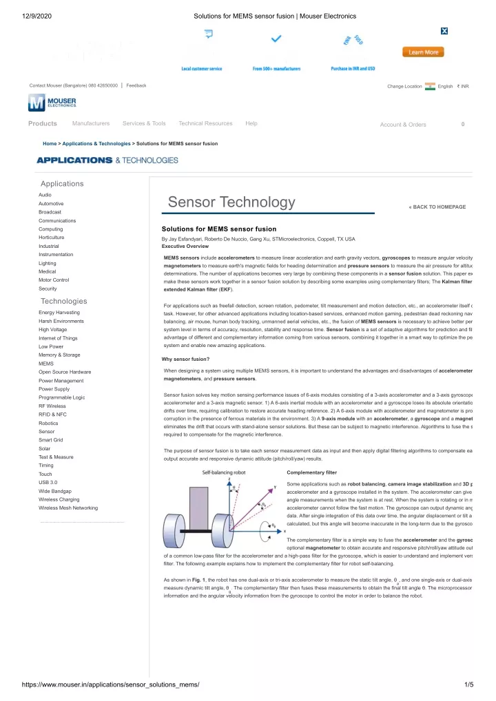
12/9/2020 Solutions for MEMS sensor fusion | Mouser Electronics Contact Mouser (Bangalore) 080 42650000 | Feedback Change Location English ₹ INR Products Manufacturers Services & Tools Technical Resources Help 0 Account & Orders Home > Applications & Technologies > Solutions for MEMS sensor fusion Applications Audio Sensor Technology Sensor Technology Automotive « BACK TO HOMEPAGE Broadcast Communications Solutions for MEMS sensor fusion Computing Horticulture By Jay Esfandyari, Roberto De Nuccio, Gang Xu, STMicroelectronics, Coppell, TX USA Executive Overview Industrial Instrumentation MEMS sensors include accelerometers to measure linear acceleration and earth gravity vectors, gyroscopes to measure angular velocity magnetometers to measure earth's magnetic fields for heading determination and pressure sensors to measure the air pressure for altitud determinations. The number of applications becomes very large by combining these components in a sensor fusion solution. This paper ex make these sensors work together in a sensor fusion solution by describing some examples using complementary filters; The Kalman filter extended Kalman filter (EKF). Lighting Medical Motor Control Security Technologies For applications such as freefall detection, screen rotation, pedometer, tilt measurement and motion detection, etc., an accelerometer itself c task. However, for other advanced applications including location-based services, enhanced motion gaming, pedestrian dead reckoning nav balancing, air mouse, human body tracking, unmanned aerial vehicles, etc., the fusion of MEMS sensors is necessary to achieve better per system level in terms of accuracy, resolution, stability and response time. Sensor fusion is a set of adaptive algorithms for prediction and fil advantage of different and complementary information coming from various sensors, combining it together in a smart way to optimize the pe system and enable new amazing applications. Energy Harvesting Harsh Environments High Voltage Internet of Things Low Power Memory & Storage Why sensor fusion? MEMS When designing a system using multiple MEMS sensors, it is important to understand the advantages and disadvantages of accelerometer magnetometers, and pressure sensors. Open Source Hardware Power Management Power Supply Sensor fusion solves key motion sensing performance issues of 6-axis modules consisting of a 3-axis accelerometer and a 3-axis gyroscope accelerometer and a 3-axis magnetic sensor. 1) A 6-axis inertial module with an accelerometer and a gyroscope loses its absolute orientatio drifts over time, requiring calibration to restore accurate heading reference. 2) A 6-axis module with accelerometer and magnetometer is pro corruption in the presence of ferrous materials in the environment. 3) A 9-axis module with an accelerometer, a gyroscope and a magnet eliminates the drift that occurs with stand-alone sensor solutions. But these can be subject to magnetic interference. Algorithms to fuse the s required to compensate for the magnetic interference. Programmable Logic RF Wireless RFID & NFC Robotics Sensor Smart Grid Solar The purpose of sensor fusion is to take each sensor measurement data as input and then apply digital filtering algorithms to compensate ea output accurate and responsive dynamic attitude (pitch/roll/yaw) results. Test & Measure Timing Complementary filter Touch USB 3.0 Some applications such as robot balancing, camera image stabilization and 3D p accelerometer and a gyroscope installed in the system. The accelerometer can give angle measurements when the system is at rest. When the system is rotating or in m accelerometer cannot follow the fast motion. The gyroscope can output dynamic ang data. After single integration of this data over time, the angular displacement or tilt a calculated, but this angle will become inaccurate in the long-term due to the gyrosco Wide Bandgap Wireless Charging Wireless Mesh Networking The complementary filter is a simple way to fuse the accelerometer and the gyrosc optional magnetometer to obtain accurate and responsive pitch/roll/yaw attitude out of a common low-pass filter for the accelerometer and a high-pass filter for the gyroscope, which is easier to understand and implement vers filter. The following example explains how to implement the complementary filter for robot self-balancing. As shown in Fig. 1, the robot has one dual-axis or tri-axis accelerometer to measure the static tilt angle, θ , and one single-axis or dual-axis measure dynamic tilt angle, θ . The complementary filter then fuses these measurements to obtain the final tilt angle θ. The microprocessor information and the angular velocity information from the gyroscope to control the motor in order to balance the robot. a g https://www.mouser.in/applications/sensor_solutions_mems/ 1/5
12/9/2020 Solutions for MEMS sensor fusion | Mouser Electronics The complementary filter block diagram is shown in Fig. 2 with a dual-axis accelerometer and a single-axis gyroscope configuration. (1) Where, a and a are normalized acceleration values in the range of [-1g +1g] after applying zero-g offset and scale factor calibration param accelerometer raw data, θ is the tilt angle in degrees. a y z (2) Where, ω is the gyroscope angular velocity raw data and ω sampling time interval, θ is the angular displacement in degrees. g is the zero-rate level in the unit of LSBs, S is the sensitivity in the unit of °/s/L X0 X Now the final tilt angle from the complementary filter will look like the following, (3) Where, β is a constant between 0 and 1. Let β be 0.95, then Equation (3) becomes, (4) The first part of Eq. 4 works like a high-pass filter (HPF) that allows the robot's dynamic motion to pass through the gyroscope. The second p low-pass filter (LPF) that allows the robot's static or quasi-static motion to pass through the accelerometer. If the accelerometer and gyroscope data are sampled at 100Hz, then the time interval ΔT is 0.01 second. So the time constant of the com is (5) The complementary filter can be considered as a simple filter by weighting the accelerometer data and gyroscope data. When the motion is 0.19 second time period, the gyroscope integration for angular displacement calculation θ is weighted more and the accelerometer noise is When the motion is slower than the 0.19 second time period, the accelerometer tilt measurement θ has more weight than the θ of gyrosco gyroscope bias drift impact from the vertical point. g a g Therefore, the tilt angle estimate from the complementary filter is accurate and responsive. It is not sensitive to the linear horizontal accelera gyroscope drift. This filter is easy to implement in a microcontroller compared to a Kalman filter. It can also be expanded to fuse multiple axe and gyroscope data. When the zero-rate level or bias ω constant offset that can be compensated from the accelerometer tilt measurement [1]. If the bias is drifting over time and temperature, then t tilt angle from the complementary filter will grow over time. In this case, ω out gyroscope turn-on to turn-on bias instability. In addition, when the robot is stationary during the operation, new ω to cancel out bias in-run stability and short-term angular random walk [2]. of gyroscope is constant and the robot is stationary, the tilt angle from the complementary filter output w X0 needs to be obtained when the robot is powered on and is statio X0 can be obtained - aga X0 Kalman filter The Kalman filter is a mathematical method invented by Dr. Rudolf E. Kalman. Since its introduction in 1960, the Kalman filter has been imp many applications. The most well-known application is the GPS receiver itself and later, the integration of GPS with the inertial navigation sy recursive digital algorithm is used to integrate or fuse GPS measurement with accelerometer and gyroscope data to achieve optimal overall performance. The Kalman filter algorithm produces estimates of the true values of sensor measurements and their associated calculated values by predi estimating the uncertainty of the predicted value, and computing a weighted average of the predicted value and the measured value. The mo given to the value with the least uncertainty. The estimates produced by the algorithm tend to be closer to the true values than the original m because the weighted average has a better estimated uncertainty than either of the values that went into the weighted average. Compared to the complementary filter, the Kalman filter requires a sound mathematical background including random signal processing, m control theory. This section of the paper gives the basic discrete Kalman filter algorithm and the implementation for robot balancing as an ex The Kalman filter tries to estimate the state x of a discrete-time controlled process that is governed by the linear difference equation [3], https://www.mouser.in/applications/sensor_solutions_mems/ 2/5
12/9/2020 Solutions for MEMS sensor fusion | Mouser Electronics (6) Where A is an n by n matrix that relates the state at the previous time step k - 1 to the state at the current step k, in the absence of either a driving f process noise. B is an n by l matrix that relates the optional control input u to the state x. H is an n by m matrix that relates the state to the measurement z . k w is the process noise (random variables). k v is the measurement noise (random variables). k w and v are assumed to be independent of each other, white, and with normal probability distributions so that, p(w) ~ N(0, Q) p(v) ~ N(0, R) where Q is the process noise covariance matrix and R is the measurement noise covariance matrix In Fig. 3, the Kalman filter algorithm is based on a linear dynamic system, which means that the matrices A, B and H are constant. To keep process and measurement covariance Q and R are also assumed as constant. Then the calculated Kalman gain K , each time step will weig measurement continuously to maintain the minimum error covariance matrix P so that the updated states will be accurate and responsive. k k Let's go back to the robot balancing example and try to implement the Kalman filter to fuse the accelerometer data and the gyroscope data f application. The first step is to construct the states and the measurement Eq. 6. Obviously, the final tilt angle θ is the state that we are going to estimate compensate gyroscope bias ω dynamically. This is the other state we are interested in. In addition, we want to use accelerometer measure the final tilt angle so that it will not drift over time due to the gyroscope random drift. X0 Let b = ω rewritten as, and assuming that the gyroscope bias is constant coupled with white noise. Let gyroscope measurement ω as the input u . The X0 X k (7) where ΔT is the sampling time interval. For example, when the gyroscope data is sampled at 100Hz, then ΔT = 0.01 second. According to Eq. 1, the measurement can be written as, (8) Combining Equation (7) and (8), then Equation (6) can be constructed as, (9) From Eq. 9, we can see matrices A, B and H are constant so that the system is linear. The second step is to obtain the process covariance matrix Q from the offline experiments on the gyroscope and measurement covariance R experiments on the accelerometer. (10) The third step is to implement the Kalman filter algorithm shown in Fig. 3 in a microprocessor with the initial values of x and P . 0 0 The final step is to test the performance of the Kalman filter. Because the gyroscope bias is optimally estimated in the loop, the robot tilt ang Kalman filter will always be accurate and will not drift away once the Kalman filter parameters Q and R are fine tuned. Extended Kalman filter Some of the most interesting and successful applications of Kalman filtering have been situations where the process is estimated and/or the relationship to the process is non-linear. A Kalman filter that linearizes the current mean and covariance is referred to as an extended Kalma something akin to a Taylor series, we can linearize the estimation around the current estimate using the partial derivatives of the process an functions to compute estimates even in the face of non-linear relationships [3]. This paper will not cover the EKF algorithm. Instead, this section of the paper will illustrate a quaternion-based EKF design for fusing accele gyroscope and magnetometer data, assuming that readers have the mathematics background of rotation matrix between body frame and loc https://www.mouser.in/applications/sensor_solutions_mems/ 3/5
12/9/2020 Solutions for MEMS sensor fusion | Mouser Electronics reference quaternio angles. When a accelero gyrosco magneto installed system a module, method [ matrix ca on gyros measure generally doesn't h singulari Euler an impleme Figure 3. Kalman filter recursive algorithm [3]. MEMS sensor data and then to update the quaternion and gyroscope bias to output attitude information for pitch, roll and yaw. This is the so-called attitude heading refer (AHRS). STMicroelectronics has a 9-axis MEMS sensor demonstration board available, dub (iNErtial MOdule V2) [5]. The quaternion-based EKF has been implemented in an S microcontroller for AHRS, as shown in Fig. 4. When the board is rotating in 3D spa will follow the motion and output real-time accurate dynamic pitch/roll/yaw values tog quaternion values. The following presents the brief EKF design procedures in the iNe Detailed EKM algorithms can be found in [4]. Figure 4. AHRS example in iNemo V2 platform. To design the EKF, the following steps are needed: 1. Define the states and measurements using quaternion method; 2. Construct the system dynamic model and the relationship between the measurements and the states; 3. Linearize and discretize the system model and then calculate the Jacobian matrices for the matrix A, B and H at each time step k [4]; 4. Get the normalized quaternion values; and 5. Calculate the Euler angles pitch/roll/yaw. Conclusion When multiple MEMS sensors are included in a system, it is necessary to implement sensor fusion algorithms to take advantage of individu capabilities for better overall performance. For Kalman filter and EKF, different system models with different sensor bias models can be des basic recursive algorithms remain the same. Kalman filter and EKF can be considered as core to the sensor fusion scheme. From the performance point of view, EKF is the best solution. However, it requires the most computation load, which consumes a lot of powe being smart phones. The trade-off between performance and power consumption is always a deciding factor with respect to which sensor fu use. References 1. Massachusetts Institute of Technology, White paper: "The Balance Filter," June 2007, http://web.mit.edu/scolton/www/filter.pdf 2. STMicroelectronics, Inc., White paper: "Introduction to MEMS gyroscopes," Nov. 2010 http://www.electroiq.com/index/display/nanotech-ar display/4659348781/articles/small-times/nanotechmems/mems/sensors/2010/11/introduction-to-mems-gyroscopes.html 3. University of North Carolina, "An Introduction to the Kalman Filter," July 2006 http://www.cs.unc.edu/~welch/media/pdf/kalman_intro.pdf 4. IEEE transaction on biomedical engineering, Vol. 53, No. 7, July 2006, "Quaternion-Based Extended Kalman Filter for Determining Orient and Magnetic Sensing," http://ieeexplore.ieee.org/xpl/freeabs_all.jsp?arnumber=1643403 5. STMicroelectronics, Inc., "iNemo - iNErtial MOdule V2 demonstration board on MEMS sensors," http://www.st.com/internet/evalboard/pro Biographies Jay Esfandyari received his Master's and PhD in EE from the U. of Technology, Vienna, and is MEMS product marketing manager at STMic 750 Canyon Dr., Coppell, TX 75019 USA; ph.: 972-971-4969; email jalinous.esfandyari@st.com. Roberto De Nuccio received his Master's in telecommunication engineering from the U. of Pisa, Italy, and is a business development mana STMicroelectronics. Gang Xu received his PhD from Shanghai Jiao Tong U., and is a senior application engineer at STMicroelectronics. Solid State Technology, Volume 54, Issue 7, July 2011 Return to Sensor Technology Homepage https://www.mouser.in/applications/sensor_solutions_mems/ 4/5
12/9/2020 Solutions for MEMS sensor fusion | Mouser Electronics https://www.mouser.in/applications/sensor_solutions_mems/ 5/5