Download
1 / 4
50 likes | 91 Vues
https://www.irjet.net/archives/V6/i2/IRJET-V6I209.pdf

E N D
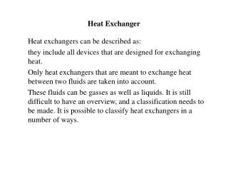
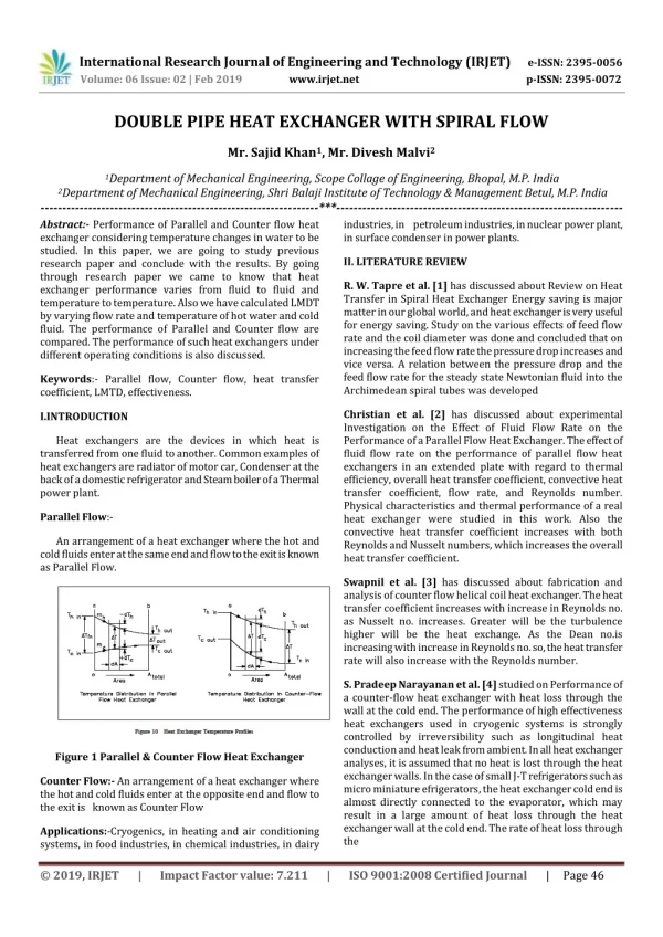
International Research Journal of Engineering and Technology(IRJET) e-ISSN: 2395-0056 Volume: 06 Issue: 02 | Feb 2019 www.irjet.net p-ISSN: 2395-0072 DOUBLE PIPE HEAT EXCHANGER WITH SPIRAL FLOW Mr. Sajid Khan1, Mr. Divesh Malvi2 1Department of Mechanical Engineering, Scope Collage of Engineering, Bhopal, M.P. India 2Department of Mechanical Engineering, Shri Balaji Institute of Technology & Management Betul, M.P. India ----------------------------------------------------------------***------------------------------------------------------------------ Abstract:- Performance of Parallel and Counter flow heat exchanger considering temperature changes in water to be studied. In this paper, we are going to study previous research paper and conclude with the results. By going through research paper we came to know that heat exchanger performance varies from fluid to fluid and temperature to temperature. Also we have calculated LMDT by varying flow rate and temperature of hot water and cold fluid. The performance of Parallel and Counter flow are compared. The performance of such heat exchangers under different operating conditions is also discussed. industries, in petroleum industries, in nuclear power plant, in surface condenser in power plants. II. LITERATURE REVIEW R. W. Tapre et al. [1] has discussed about Review on Heat Transfer in Spiral Heat Exchanger Energy saving is major matter in our global world, and heat exchanger is very useful for energy saving. Study on the various effects of feed flow rate and the coil diameter was done and concluded that on increasing the feed flow rate the pressure drop increases and vice versa. A relation between the pressure drop and the feed flow rate for the steady state Newtonian fluid into the Archimedean spiral tubes was developed Keywords:- Parallel flow, Counter flow, heat transfer coefficient, LMTD, effectiveness. Christian et al. [2] has discussed about experimental Investigation on the Effect of Fluid Flow Rate on the Performance of a Parallel Flow Heat Exchanger. The effect of fluid flow rate on the performance of parallel flow heat exchangers in an extended plate with regard to thermal efficiency, overall heat transfer coefficient, convective heat transfer coefficient, flow rate, and Reynolds number. Physical characteristics and thermal performance of a real heat exchanger were studied in this work. Also the convective heat transfer coefficient increases with both Reynolds and Nusselt numbers, which increases the overall heat transfer coefficient. I.INTRODUCTION Heat exchangers are the devices in which heat is transferred from one fluid to another. Common examples of heat exchangers are radiator of motor car, Condenser at the back of a domestic refrigerator and Steam boiler of a Thermal power plant. Parallel Flow:- An arrangement of a heat exchanger where the hot and cold fluids enter at the same end and flow to the exit is known as Parallel Flow. Swapnil et al. [3] has discussed about fabrication and analysis of counter flow helical coil heat exchanger. The heat transfer coefficient increases with increase in Reynolds no. as Nusselt no. increases. Greater will be the turbulence higher will be the heat exchange. As the Dean no.is increasing with increase in Reynolds no. so, the heat transfer rate will also increase with the Reynolds number. S. Pradeep Narayanan et al. [4] studied on Performance of a counter-flow heat exchanger with heat loss through the wall at the cold end. The performance of high effectiveness heat exchangers used in cryogenic systems is strongly controlled by irreversibility such as longitudinal heat conduction and heat leak from ambient. In all heat exchanger analyses, it is assumed that no heat is lost through the heat exchanger walls. In the case of small J-T refrigerators such as micro miniature efrigerators, the heat exchanger cold end is almost directly connected to the evaporator, which may result in a large amount of heat loss through the heat exchanger wall at the cold end. The rate of heat loss through the Figure 1 Parallel & Counter Flow Heat Exchanger Counter Flow:- An arrangement of a heat exchanger where the hot and cold fluids enter at the opposite end and flow to the exit is known as Counter Flow Applications:-Cryogenics, in heating and air conditioning systems, in food industries, in chemical industries, in dairy © 2019, IRJET | Impact Factor value: 7.211 | ISO 9001:2008 Certified Journal | Page 46
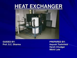
International Research Journal of Engineering and Technology(IRJET) e-ISSN: 2395-0056 Volume: 06 Issue: 02 | Feb 2019 www.irjet.net p-ISSN: 2395-0072 conduction through wall, heat in leak from wall at the cold end is also strongly dependent on the longitudinal thermal resistance of the wall. In this paper, they present the relationship between the effectiveness of a heat exchanger losing heat at the cold end and other resistances such as number of transfer units (NTU), longitudinal thermal resistance etc. The performance of such heat exchangers under different operating conditions is also discussed. dominated by the volume flow rate and nanoparticles did not contribute to extra heat absorption. It means that, at high flow rate they found that the nanoparticles could not absorb more heat than water cooled counter flow heat exchanger III. EXPERIMENTAL SETUP Setup Specifications:- 1) Digital Temp. Indicator: 200 0C -1 No. Prabhat et al. [5] studied on a performance evaluation of counter flow heat exchanger considering for low temp application. He found those Counter flow heat exchangers are commonly used in cryogenic systems because of their high effectiveness. They observed that losses such longitudinal surrounding, flow maldistribution etc. They extended their study to understand quantitative effect of heat in leak and axial conduction parameters on degradation of heat exchanger performance for 300-80k and 80-20k temperature range. 2) Geyser for hot water 3) Inner tube: I. D. – 12 mm 4) Outer tube: O.D. –13.5mm. 5) Length of the heat exchanger – 1.5 m. 6) Ball valves for flow arrangement. J. Kragh et al. [6] studied about New counter flow heat exchanger designed for ventilation systems in cold climates. The work of designing a high effective heat exchanger capable of continuously defrosting itself seems to be successful. Good accordance between the calculated and measured efficiency was found at dry condition. To minimize the energy cost, a more efficient way to solve the freezing problem is therefore desirable. In this paper, the construction and test measurements of a new counter flow heat exchanger designed for cold climates are presented. The developed heat exchanger is capable of continuously defrosting itself without using supplementary heating. Other advantages of the developed heat exchanger are low pressure loss, cheap materials and a simple construction. Fig. Double Pipe Heat Exchanger with Spherical Coil 7) Outer G.I.Inner lenght - 1.25 m 8) Outer G.I.Inner Dia - 35mm The disadvantage is that the exchanger is big compared with other heat exchangers. 9) Outer G.I.Outer Dia - 37 mm P.C. Mukeshkumar et al. [7] has discussed about the experimental study on parallel and counter flow configuration of a shell and helically coiled tube heat exchanger using Al2O3 / water nanofluid. This study was done by changing the parallel flow configuration into counter flow configuration under laminar flow regime. The Al2O3 / water nanofluid at 0.4% and 0.8% particle volume concentration were prepared by using two step methods. The overall heat transfer coefficient is 5-9% higher than that of parallel flow at 0.8% nanofluid Mushtag I. 10) Spring Length - 1.25m 11) Spring pitch - 12mm 12) wire Coil Dia. - 4mm 13) Spring Coil Dia. - 33mm 14) Digital Temp. Indicator (PTD) - 2000C -1 No. 15) A meter - 30A Hasan et al. [8] studied about Investigation of a counter flow micro channel heat exchanger performance with using nanofluid as coolant. In this paper the performance of counter flow micro channel heat exchanger (CFMCHE) is numerically investigated with a Nano fluid as cooling medium. Two types of Nano-fluids are used a: Cu- water b: Al2O3. They found that nanofluid cooled CFMHE when the flow rate was low. For high flow ate the heat transfer was 16) V meter -300V 17) Pressure gauge -1 kg, 2kg 18) Digital temperature indicator - 8 point (19)Geyser for hot water -2000 w, 8 bar © 2019, IRJET | Impact Factor value: 7.211 | ISO 9001:2008 Certified Journal | Page 47
International Research Journal of Engineering and Technology(IRJET) e-ISSN: 2395-0056 Volume: 06 Issue: 02 | Feb 2019 www.irjet.net p-ISSN: 2395-0072 IV. PROPOSED WORK 4- Adjust the cold water flow rate to 1000 cc/min The apparatus is a conventional tube in tube type of heat exchanger. In this heat exchanger hot fluid flows through inner tube and cooling water flows through the annulus. The apparatus is mounted on a board & is provided with a system of pipes & valves. 5- Take readings of the hot and the cold water at inlet, mid point and outlet once conditions have stabilized Readings; Tempreture Thi Tho Tci Tco 60oC 60oC 53oC 35oC 37oC PART B Repeat Part A for counter flow conditions and compare the results. PART C PROCEDURE 1.Set the hot and cold fluids in counter flow across the heat exchanger. Parallel & Counter type of flow arrangement can be done by opening & closing of ball valves as per requirement. Hot fluid flows always in one direction & cold fluid flow direction can be changed from either parallel flow to counter flow or vice versa. 2.Adjust the hot water flow rate to 2000 cc/min . 3.Adjust the cold water flow rate to 2000 cc/min. 4.Set the hot water temperature to 50 ºC and take reading of the water temperature. 5.Increase the hot water temperature in increments of 10 ºC and repeat the above steps. 6.Tabulate the readings as in part A. PART D PROCEDURE 1.Set the hot and cold fluids in counter flow across the heat exchanger C. Temperature Indicator along with selector switch is provided for measurement of temperature of hot fluid & cold fluid. An electric geyser is used to heat the water. Outer tube of the heat exchanger is provided with adequate insulation to minimize the heat the heat losses. Material used for the construction in G.I. The flow arrangement for parallel & counter flow. 2.Set the hot water temperature control to 60. 3.Set the hot water flow rate at a constant value of 2000 cc/min. 4.Adjust the cold water flow rate to 1000 cc/min and take reading of the water temperatures. PROCEDURE 5.Increase the flow rate of cold water in steps of 1000 cc/min and take reading of the water temperatures. PART A PROCEDURE 1- 6.Tabulate the readings. Set the hot and cold fluids in parallel flow across the heat exchanger C Qc Thi (0C) Tho(0C) Tci(0C) Tco(0C) (cc/min) 2- Set the hot water temperature control to 60 0C 2000 55 45 27 38 3- Adjust the hot water flow rate to 2000 cc/min © 2019, IRJET | Impact Factor value: 7.211 | ISO 9001:2008 Certified Journal | Page 48
International Research Journal of Engineering and Technology(IRJET) e-ISSN: 2395-0056 Volume: 06 Issue: 02 | Feb 2019 www.irjet.net p-ISSN: 2395-0072 1. Heat transfer is more in case of counter flow heat exchanger using water or any other oil as heat carrying medium. PART E (optional) Repeat Part D for parallel flow conditions CALCULATIONS 2. Most of the research is done taking water as a working fluid both as heat carrying & heat absorbing medium. 1.Calculate as in part A and tabulate the results., Tm, U, and h q , c q, 2.Draw the temperature profiles of the hot and cold fluids along the heat exchanger. 3.Comment on the results obtained. VII. REFERENCES [1]R. W. Tapre, Dr.Jayant P. Kaware. “Review on Heat Transfer in Spiral Heat Exchanger”, International Journal of Scientific and Research Publications, Volume 5, Issue 6, June 2015 qh qc Ƞ ∆Tm U ɛ [2]Christian O. Osueke, Anthony O. Onokwai Adeyinka O. Adeoye. “Experimental Investigation on the Effect of Fluid Flow Rate on the Performance of a Parallel Flow Heat Exchanger”, International Journal of Innovative Research in Advanced Engineering (IJIRAE) Issue 6, Volume 2 (June 2015) 8.671 (watt) 3.342 (watt) 0.385 6.805(0C) 0.374(W/m2- 0.094 0C) VI. CONCLUSIONS Experimental investigations of heat transfer characteristics of double pipe heat exchanger fitted with inserted concentric tubes for parallel & counter flow. The review indicates that Heat Exchangers are the heat transfer devices which are used in different applications. The heat exchangers [3]Swapnil Ahire, Purushottam Shelke, Bhalchandra Shinde, Nilesh Totala. “Fabrication and Analysis of Counter Flow Helical Coil Heat Exchanger”, International Journal of Engineering Trends and Technology (IJETT) – Volume 15 Number 5 – Sep 2014 Water flow rate. Increase in cold water mass flow rate for constant hot water mass flow rate resulted in increase in effectiveness. For both helical coil and straight tube heat exchangers with parallel and counter flow configuration this result obtained [4]S. Pradeep Narayanan, G. Venkatarathnam. “Performance of a counterflow heat exchanger with heat loss through the wall at the cold end”, Elsevier Science Cryogenics 39 (1999) Page No. - 43–52 1) The effectiveness of heat exchanger greatly affected by hot water mass flow rate and cold is most effective in all these conditions and straight tube parallel flow heat exchanger is least effective. [5]Prabhat Gupta, M.D. Atrey. “Performance evaluation of counter flow heat exchangers considering the effect of heat in leak and longitudinal conduction for low-temperature applications”, Elsevier Science , Cryogenics 40 (2000) Page No.- 469-474 2) Helical coil counter flow can be used to recover the resources like water as it is converted into the steam which is condensed by using the condenser. Heat exchangers also useful for the economical running of industries and to control the pollution as in case of economizer and air pre- heater. A good agreement is obtained between the experimental results of counter & parallel flow in that counter flow is more efficient for same flow rate. [6]J. Kragh, J. Rose, T.R. Nielsen, S. Svendsen. “New counter flow heat exchanger designed for ventilation systems in cold climates”, Elsevier Science Energy and Buildings 39 (2007) Page No.- 1151–1158 [7]P.C. Mukeshkumar, J. Kuma, S. Suresh, K. Praveen babu. “Experimental study on parallel and counter flow configuration of a shell and helically coiled tube heat exchanger using Al2O3 / water nanofluid”, J. Mater. Environ. Sci., Volume-3, Issue-4, 2012, Page No.-766-775 3) Helical coil counter flow heat exchanger's effectiveness is 22-24 % higher than straight tube parallel flow heat exchanger, 5-7% than straight tube counter flow, 14-17% than helical coil parallel flow heat exchanger under same operating conditions. [8]Mushtaq I. Hasan, Abdul Muhsin A. Rageb, Mahmmod Yaghoubi. “Investigation of a Counter Flow Micro-channel Heat Exchanger Performance with Using Nanofluid as a Coolant”, Journal of Electronics Cooling and Thermal Control, volume-2, 2012, Page No.-35-43 4) Straight tube counter flow heat exchanger's effectiveness is 7-10% higher than helical coil parallel flow heat exchanger. From the literature review of experimental investigation of performance of parallel & counter flow heat exchanger we came to the conclusion that: © 2019, IRJET | Impact Factor value: 7.211 | ISO 9001:2008 Certified Journal | Page 49