Download
1 / 14
140 likes | 161 Vues
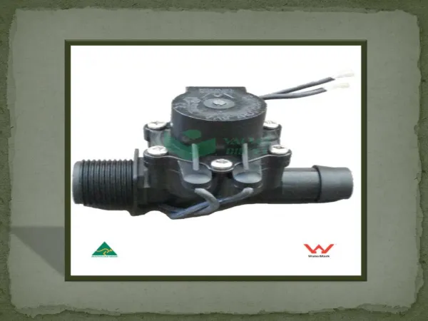
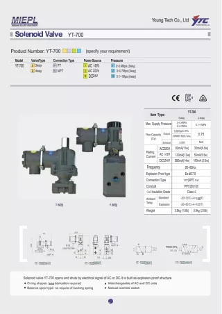
"ITEM: V415517D-C313A<br><br>*High performance, compact design<br>*Flexible sub-base system<br>*Multipressure system capability<br>*Wide range of accessories<br>*Easy to convert from internal to external pilot supply<br>*Valve exchange under pressure<br><br>Flow:650.00 l/min<br>Operation:5/2<br>Actuation:Sol/Spring<br>Standard:ISO 15407-1;VDMA 24 563<br>Voltage:24Vdc"<br>For More Information visit on our website:- www.instronline.com<br>Our E-mail Address:-info@instronline.com <br>

E N D
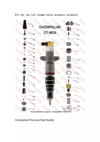
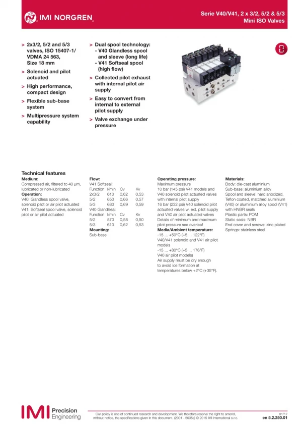
Serie V40/V41, 2 x 3/2, 5/2 & 5/3 Mini ISO Valves > 2x3/2, 5/2 and 5/3 valves, ISO 15407-1/ VDMA 24 563, Size 18 mm > Solenoid and pilot actuated > High performance, compact design > Flexible sub-base system > Multipressure system capability > Dual spool technology: - V40 Glandless spool and sleeve (long life) - V41 Softseal spool (high flow) > Collected pilot exhaust with internal pilot air supply > Easy to convert from internal to external pilot supply > Valve exchange under pressure Technical features Medium: Compressed air, filtered to 40 µm, lubricated or non-lubricated Operation: V40: Glandless spool valve, solenoid pilot or air pilot actuated V41: Softseal spool valve, solenoid pilot or air pilot actuated Flow: V41 Softseal: Function l/min Cv 2x3/2 610 5/2 650 5/3 680 V40 Glandless: Function l/min Cv 5/2 570 5/3 610 Mounting: Sub-base Operating pressure: Maximum pressure 10 bar (145 psi) V41 models and V40 solenoid pilot actuated valves with internal pilot supply 16 bar (232 psi) V40 solenoid pilot actuated valves w. ext. pilot supply and V40 air pilot actuated valves Details of minimum and maximum pilot pressure see overleaf Media/Ambient temperature: -15 ... +50°C (+5 ... 122°F) V40/V41 solenoid and V41 air pilot models -15 ... +80°C (+5 ... 176°F) V40 air pilot models) Air supply must be dry enough to avoid ice formation at temperatures below +2°C (+35°F). Materials: Body: die-cast aluminium Sub-base: aluminium alloy Spool and sleeve: hard anodized, Teflon coated, matched aluminium (V40) or aluminium alloy spool (V41) with HNBR seals Plastic parts: POM Static seals: NBR End cover and screws: zinc plated Springs: stainless steel Kv 0,53 0,57 0,59 0,62 0,66 0,69 Kv 0,50 0,53 0,58 0,62 Our policy is one of continued research and development. We therefore reserve the right to amend, without notice, the specifications given in this document. (2001 - 5035e) © 2015 IMI International s.r.o. 01/17 en 5.2.250.01
Serie V40/V41, 2 x 3/2, 5/2 & 5/3 Mini ISO Valves 2 x 3/2 Solenoid pilot actuated softseal valves Symbol Function 2 x 3/2 Actuation/ return Pilot supply Pilot exhaust Operating pressure (bar) Pilot pressure (bar) Flow (l/min) Model NC Solenoid/Spring Internal Collected # 2,5 ... 10 – 610 V415A11D-*1) 410 2 14 10 12 84 82 5 1 3 NC Solenoid/Spring External Not collected 0 ... 10 1,7 + (0,35 x operating pressure) 610 V415A22D-*1) 410 2 14 10 12 84 82 14 5 1 3 NO Solenoid/Spring Internal Collected # 2,5 ... 10 – 610 V415B11D-*1) 414 2 10 12 10 84 82 3 5 1 NO Solenoid/Spring External Not collected 0 ... 10 1,7 + (0,35 x operating pressure) 610 V415B22D-*1) 414 2 10 12 10 84 82 14 5 1 3 NO/NC Solenoid/Spring Internal Collected # 2,5 ... 10 – 610 V415C11D-*1) 410 2 14 12 10 84 82 3 5 1 NO/NC Solenoid/Spring External Not collected 0 ... 10 1,7 + (0,35 x operating pressure) 610 V415C22D-*1) 410 2 14 12 10 84 82 14 5 1 3 5/2 Solenoid pilot actuated glandless and softseal valves 14 Symbol Pilot supply Pilot exhaust Operator 14 Operator 12 Operating pressure (bar) Pilot pressure (bar) Sealing system Flow (l/min) Model Internal Internal Collected # Collected # Solenoid Solenoid Air spring Air spring 1 ... 10 1 ... 10 – – Glandless Soft seal 570 650 V405513D-*1) V415513D-*1) 2 4 2 4 14 12 5 3 1 14 12 5 3 Not collected Not collected 1 3 External External Solenoid Solenoid Air spring Air spring -0,9 ... 16 -0,9 ... 10 1 ... 10 1 ... 10 Glandless Soft seal 570 650 V405523D-*1) V415523D-*1) 2 2 2 4 4 4 14 12 14 12 14 12 5 3 1 5 3 1 Collected # Collected # Internal Internal Solenoid Solenoid Spring & air spring Spring 1,6 ... 10 2 ... 10 – – Glandless Soft seal 570 650 V405516D-*1) V415517D-*1) 2 2 4 4 14 12 2 4 84 5 1 3 14 12 14 12 5 3 1 5 3 1 Not collected Not collected External External Solenoid Solenoid Spring & air spring Spring -0,9 ... 16 -0,9 ... 10 1,6 ... 10 2 ... 10 Glandless Soft seal 570 650 V405526D-*1) V415527D-*1) 2 2 4 4 14 12 12 84 3 82 84 14 5 1 Internal Internal Collected # Collected # Solenoid Solenoid Solenoid Solenoid 2 ... 10 2 ... 10 – – Glandless Soft seal 570 650 V405511D-*1) V415511D-*1) 2 4 4 14 12 84 82 5 3 1 External External Not collected Not collected Solenoid Solenoid Solenoid Solenoid -0,9 ... 16 -0,9 ... 10 2 ... 10 2 ... 10 Glandless Soft seal 570 650 V405522D-*1) V415522D-*1) 2 2 4 4 12 12 84 14 82 5 3 5 4 1 1 2 12 3 Internal Collected # Solenoid (priority) Solenoid 2 ... 10 Glandless 570 V405591D-*1) 2 4 14 12 12 84 82 5 1 3 External Not collected Solenoid (priority) Solenoid -0,9 ... 16 2 ... 10 Glandless 570 V405592D-*1) 2 4 12 84 14 82 5 1 3 *1) Insert voltage code from tables on page 3 # Pilot exhaust collected and exhausted via port 14 NO = Normally open, NC = Normally closed 12 Our policy is one of continued research and development. We therefore reserve the right to amend, without notice, the specifications given in this document. (2001 - 5035e) © 2015 IMI International s.r.o. en 5.2.250.02 01/17
Serie V40/V41, 2 x 3/2, 5/2 & 5/3 Mini ISO Valves 5/3 Solenoid pilot actuated glandless and softseal valves 2 4 14 12 Symbol Function Pilot Pilot exhaust Operator 14 Operator 12 Operating pressure (bar) Pilot pressure (bar) Sealing system Flow (l/min) Model supply 5 3 1 APB APB Internal Internal Collected # Collected # Solenoid Solenoid Solenoid Solenoid 2 ... 10 2 ... 10 – – Glandless Soft seal 610 680 V405611D-*1) V415611D-*1) 2 2 2 4 4 14 12 14 12 5 3 1 5 3 External External 1 APB APB Not collected Not collected Solenoid Solenoid Solenoid Solenoid -0,9 ... 16 -0,9 ... 10 2 ... 10 2 ... 10 Glandless Soft seal 610 680 V405622D-*1) V415622D-*1) 2 2 4 4 2 4 14 14 12 12 14 12 5 5 3 1 1 3 COE COE Internal Internal Collected # Collected # Solenoid Solenoid Solenoid Solenoid 2 ... 10 2,5 ... 10 – – Glandless Soft seal 610 680 V405711D-*1) V415711D-*1) 2 2 2 4 4 4 14 12 5 3 5 3 1 1 14 12 14 COE COE External External Not collected Not collected Solenoid Solenoid Solenoid Solenoid -0,9 ... 16 -0,9 ... 10 2 ... 10 2,5 ... 10 Glandless Soft seal 610 680 V405722D-*1) V415722D-*1) 2 2 4 4 12 5 3 5 3 1 1 14 12 COP COP Internal Internal Collected # Collected # Solenoid Solenoid Solenoid Solenoid 2 ... 10 2 ... 10 – – Glandless Soft seal 610 680 V405811D-*1) V415811D-*1) 2 4 14 12 14 12 5 3 1 COP COP External External Not collected Not collected Solenoid Solenoid Solenoid Solenoid -0,9 ... 16 -0,9 ... 10 2 ... 10 2 ... 10 Glandless Soft seal 610 680 V405822D-*1) V415822D-*1) 2 4 14 14 12 5 3 1 *1) Insert voltage code from tables below # Pilot exhaust collected and exhausted via port 14 APB = All Ports Blocked COE = Centre Open Exhaust COP = Centre open pressure Electrical details for solenoid operators Voltage codes & spare pilots Voltage tolerances Rating Inlet orifice Electrical connection Manual override Voltage 12 V d.c. 24 V d.c. 24 V 50/60 Hz. 48 V 50/60 Hz 110 V d.c. 115 V 50/60 Hz 230 V 50/60 Hz Coil code C312A C313A C314A C316A C317A C318A C319A Current 1 W 1,2 W 2,1/1,5 VA 2,1/1,5 VA 1 W 2,1/1,5 VA 2,1/1,5 VA Spare pilot valve VZC7L2C1-C312A VZC7L2C1-C313A VZC7L2C1-C314A VZC7L2C1-C316A VZC7L2C1-C317A VZC7L2C1-C318A VZC7L2C1-C319A -10%/+15% 100 % Continuous duty 0,8 mm 15 mm DIN EN 175301-803 (DIN 43 650) Table C Shrouded push button, spring return Convertible into lockable type with set-up kit, part no. V70532-K00 (see next page) Protection class Materials IP 65 with sealed plug (ISO 6952) NEMA 4 PPS (body), FPM and NBR (seal) Other voltages available on request. Spare pilot valves are delivered with mounting screws. Intrinsically safe version available on request. Our policy is one of continued research and development. We therefore reserve the right to amend, without notice, the specifications given in this document. (2001 - 5035e) © 2015 IMI International s.r.o. en 5.2.250.03 01/17
Serie V40/V41, 2 x 3/2, 5/2 & 5/3 Mini ISO Valves 2 x 3/2 Air pilot actuated softseal valves Symbol Function 2 x 3/2 Actuation/return 2 x 3/2 Operating pressure (bar) Pilot pressure (bar) Sealing system Flow (l/min) Model 4 2 NC Air/Spring 0 ... 10 1,7 + (0,35 x operating pressure) Soft seal 610 V415A33A-X0020 10 10 14 12 5 1 3 4 2 NO Air/Spring 0 ... 10 1,7 + (0,35 x operating pressure) Soft seal 610 V415B33A-X0020 14 12 10 10 5 1 3 4 2 NO/NC Air/Spring 0 ... 10 1,7 + (0,35 x operating pressure) Soft seal 610 V415C33A-X0020 10 12 14 10 5 1 3 5/2 Air pilot actuated glandless and softseal valves Symbol Operator 14 Operator 12 Operating pressure (bar) Pilot pressure (bar) Sealing system Flow (l/min) Model Air Air Spring Spring -0,9 ... 16 -0,9 ... 10 1,6 ... 16 2 ... 10 Glandless Soft seal 570 610 V405537A-X0090 V415537A-X0090 4 212 14 5 3 1 Air Air Air Air -0,9 ... 16 -0,9 ... 10 2 ... 16 2 ... 10 Glandless Soft seal 570 610 V405533A-X0020 V415533A-X0020 4 2 14 12 5 1 3 Air (priority ) Air -0,9 ... 16 2 ... 16 Glandless 570 V405533A-X0070 4 2 14 12 5 1 3 5/3 Air pilot actuated glandless and softseal valves Symbol Function Operator 14 Operator 12 Operating pressure (bar) Pilot pressure (bar) Sealing system Flow (l/min) Model APB APB Air Air Air Air -0,9 ... 16 -0,9 ... 10 2 ... 16 2 ... 10 Glandless Soft seal 610 680 V405633A-X0020 V415633A-X0020 4 2 14 12 5 1 3 COE COE Air Air Air Air -0,9 ... 16 -0,9 ... 10 2 ... 16 2,5 ... 16 Glandless Soft seal 610 680 V405733A-X0020 V415733A-X0020 4 2 14 12 5 1 3 COP COP Air Air Air Air -0,9 ... 16 -0,9 ... 10 2 ... 16 2 ... 10 Glandless Soft seal 610 680 V405833A-X0020 V415833A-X0020 4 2 14 12 5 1 3 Valve function: NO = Normally open, NC = Normally closed APB = All Ports Blocked, COE = Centre Open Exhaust, COP = Centre Open Pressure Our policy is one of continued research and development. We therefore reserve the right to amend, without notice, the specifications given in this document. (2001 - 5035e) © 2015 IMI International s.r.o. en 5.2.250.04 01/17
Serie V40/V41, 2 x 3/2, 5/2 & 5/3 Mini ISO Valves Accessories Manual override set-up kit DIN EN 50 022 rail (1 m) DIN-rail mounting kit Blanking disc to modular sub-base Blanking plate for unused station Transition plate V40/V41 » V44/V45 Page 11 V10009-C00 (35 x 7,5 mm) V10592-C01 (35 x 15 mm) V70531-KA0 V70422-K50 (Ports 1,3,5)) V70423-K50 (Ports 12 & 14) V70532-K00 V70400-K50 V70436-K00 V70436-B00 *1) *1) With supply and exhaust ports Blanking Plug for Fixed Length Sub-base V70421-K50 (Ports 1, 3, 5) Sandwich plates Intermediate supply/ exhaust manifold Single valve shut-off plate Single pressure regulator plate Double pressure regulator plate Flow regulator plate Sandwich plate with additional pressure port 1 Page 10 Page 10 Page 12 & 13 Page 13 Page 10 Page 11 V70429-A50 (G1/8) V70429-P50 (1/8 NPTF) V70430-K50 (Port 1 blocked) V70427-K51 (Port 1 reg.) V70427-K52 (Port 2 reg.) V70427-K53 (Port 4 reg.) V70427-K54 (Ports 2+4 reg.) V70428-K50 (Ports 3+5 reg.) V70435-A50 (G1/8) V70435-P50 (1/8NPTF) Sub-bases and end plates Single station sub-base Double station modular sub-base Single station modular sub-base End plate kit Fixed length sub-base Page 7 Page 8 & 9 Page 8 & 9 Page 8 & 9 Page 9 Connector plug - ordered separately I15 mm DIN EN 175301-803 (DIN 43 650) Table C V10027-D00 250 V a.c./300 V d.c. Our policy is one of continued research and development. We therefore reserve the right to amend, without notice, the specifications given in this document. (2001 - 5035e) © 2015 IMI International s.r.o. en 5.2.250.05 01/17
Serie V40/V41, 2 x 3/2, 5/2 & 5/3 Mini ISO Valves Valve dimensions V4155*3D-C3*** 5/2 Single solenoid pilot valve Air spring return Dimensions in mm Projection/First angle V4055**D-C3*** 5/2 Single solenoid pilot valve Mechanical (& air) spring valve 77,5 77,5 35 30 30 5 5 M3 M3 115 99 57,5 41,5 EXT INT INT 12,5 18,5 12,5 18,5 INT EXT EXT 1 1 V4055**D-C3*** & V4155**D-C3*** 5/2 Double solenoid pilot valve V405***D-C3*** & V415***D-C3*** 2x3/2 + 5/3 Double solenoid pilot valve 1 Manual override 95,5 77,5 30 5 M3 115 57,5 EXT INT 18,5 12,5 EXT INT 1 1 Our policy is one of continued research and development. We therefore reserve the right to amend, without notice, the specifications given in this document. (2001 - 5035e) © 2015 IMI International s.r.o. en 5.2.250.06 01/17
Serie V40/V41, 2 x 3/2, 5/2 & 5/3 Mini ISO Valves V415537A-X0090 5/2 Single air pilot valve Dimensions in mm Projection/First angle V405537A-X0090 5/2 Single air pilot valve V405*33A-X00*0 & V415*33A-X00*0 2x3/2, 5/2 + 5/3 Double air pilot valve 99 115 41,5 57,5 35 35 30 30 5 5 M3 M3 EXT INT 18,5 12,5 INT 12,5 18,5 EXT INT EXT Single station sub-base – side ported with pilot ports 50 5 1 3 23 Port size A G1/8 side ported with pilot ports Model V70401-A5B 11 7,5 9 30 Note: Pilot ports = M5 58 66 Ø 4,2 58 13,5 12,5 26,5 2xM3 5xA Ø 4,3 4 14 4 2 12 15 2xM5 15 40 Our policy is one of continued research and development. We therefore reserve the right to amend, without notice, the specifications given in this document. (2001 - 5035e) © 2015 IMI International s.r.o. en 5.2.250.07 01/17
Serie V40/V41, 2 x 3/2, 5/2 & 5/3 Mini ISO Valves Side ported sub-base Dimensions in mm Projection/First angle 47 31,5 9,5 120,5 A C C M5 M5 M5 12 12 12 14 12 73,5 2 2 2 44,5 1 38,5 33 31 27 15 5 3 4 4 4 7,5 13,5 4,5 3,5 28 11,5 42,5 65 Bottom and side ported sub-base N = number of stations x/y = Insert port type from table below M5 1 Right hand side 2 Left hand side 14 14 14 38,5 34 Code x Code y Ports 2 & 4 Ports 7,5 A P - - - G1/8 1/8 NPTF Ø 8 mm PIF Ø 6 mm PIF Ø 1/4" PIF M5 M5 M5 M5 M5 A P 8 6 17 17 *N x 19,1 1 2 1 53,5 3,8 Ø 4,3 7,5 Our policy is one of continued research and development. We therefore reserve the right to amend, without notice, the specifications given in this document. (2001 - 5035e) © 2015 IMI International s.r.o. en 5.2.250.08 01/17
Serie V40/V41, 2 x 3/2, 5/2 & 5/3 Mini ISO Valves Modular sub-bases parts for DIN rail or surface mounting Bottom ported sub-base Dimensions in mm Projection/First angle Individual components 35,5 20,5 Modular sub-base (A) Double station modular sub-base Modular sub-base (A) Modular sub-base (B) Modular sub-base (B) Ports 2+4 on side V70425-x5F Ports 2+4 on side V70432-y5F Ports 2+4 on side Pilot ports 12+14 on side V70425-A5E V70426-x5F 4 2 11,5 Ports 2+4 on bottom Ports 2+4 on bottom End ported 2 4 Pilot ports 12+14 on side V70424-B5C (G1/4) V70426-A5E V70424-R5C (1/4NPTF) End ported end caps 1 left hand and 1 right hand End ported end caps 1 left and 1 right 4 2 End plate kit (C) Ports 2+4 on side V70431-A5F (1/3/5 G1/4, 2/4 G1/8) V70431-P5F (1/3/5 1/4NPTF, 2/4 1/8NPTF) End plate kit with valve station B D Accessories Note: Port 14 either used for external pilot air supply or for collected pilot air exhaust. Therefore, never plug port 14 when using valves with internal pilot air supply. Port 12 is not used, plugging not necessary. DIN EN 50022 rail 35 x 7,5 mm, 1m 35 x 15 mm, 1m Mounting kit Ports 1, 3, 5 Ports 12+14 V10009-C00 V10592-C01 V70531-KAO V70422-K50 V70423-K50 DIN EN 50022 rail DIN rail (D) Blanking disk to modular sub-base Blanking disk to modular sub-base Ø 8 Fixed length sub-base - bottom ported 4,5 21,5 X 21 3 20,6 62,2 1 5 21,5 B A 5,5 9,5 25 Ø 4,5 View X 20 19,1 22 Number of stations A B Ports 2 & 4 Ports 1, 3 & 5 Model 2 4 6 8 10 12 59,1 97,3 135,5 173,7 211,9 250,1 48,1 86,3 124,5 162,7 200,9 239,1 G1/8 G1/8 G1/8 G1/8 G1/8 G1/8 G1/4 G1/4 G1/4 G1/4 G1/4 G1/4 V70402-A5O V70404-A5O V70406-A5O V70408-A5O V70410-A5O V70412-A5O Note: This sub-base is suitable for solenoid pilot actuated valves with internal pilot air supply only Our policy is one of continued research and development. We therefore reserve the right to amend, without notice, the specifications given in this document. (2001 - 5035e) © 2015 IMI International s.r.o. en 5.2.250.9 01/17
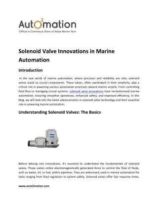
V40/V41 series, 2 x 3/2, 5/2 & 5/3 Mini ISO Valves Intermediate supply/exhaust manifold Single valve shut-off plate Dimensions in mm Projection/First angle 5,5 20,5 9,3 M3 5 17 45 23 9,15 18,6 8 M3 9,3 10,6 3 1 5 3 x A 25 12,5 31 12,5 18,6 73,2 56 Port size A G1/8 Model V70429-A5O Symbol Description Single shut-off plate supplied with gasket Model V70430-K5O Provides additional porting on modular- or fixed length sub-base. Occupies one valve station. Supplied with gasket for both sub-bases. Can be used to: Improve supply flow Increase exhaust capacity Pneumatically separate valves for fail-safe emergency Multipressure system and system solutions Allows individual exchange of valve, while valve island is pressurised by port 1. Note: Flow restricted to max. 240 l/min. Flow characteristics for pressure regulator plates Flow regulator plate 76 6,1 Dual regulation of exhaust ports 3 & 5 Exhaust flow (ports 3+5) [l/min] 450 400 350 15,5 M3 300 7,5 250 5 38 200 150 100 50 0 0 1 2 3 4 5 6 7 8 9 10 11 12 Number of turns from closed 12,5 18,6 Flow: Port 1 > 2 & 1> 4: remains unchanged Flow measured at 6 bar inlet, pressure drop 1 bar Symbol Description Flow regulator supplied with gasket Model V70428-K5O Our policy is one of continued research and development. We therefore reserve the right to amend, without notice, the specifications given in this document. (2001 - 5035e) © 2015 IMI International s.r.o. en 5.2.250.10 01/17
Serie V40/V41, 2 x 3/2, 5/2 & 5/3 Mini ISO Valves Sandwich plate with additional pressure port 1 Blanking plate Dimensions in mm Projection/First angle 13 10 4 M3 12,5 18 48 Description Blanking plate for blocking of unused stations (supplied with gasket) Model V70400-K5O Description Sandwich plate with additional port 1 G1/8, supplied with gasket Model V70435-A5O Transition plate #18 mm > #26 mm 90 65 27,1 3,5 10,6 55 V44/45 V40/41 V44/45 17,6 5 1 3 Description Transition plate V40/V41 » V44/V45 Without port 1/3/5 Transition plate V40/V41 » V44/V45 with supply/exhaust ports G1/4 Model V70436-K0O V70436-B00 3 x G1/4" V40/41 22,4 39,6 73,7 Our policy is one of continued research and development. We therefore reserve the right to amend, without notice, the specifications given in this document. (2001 - 5035e) © 2015 IMI International s.r.o. en 5.2.250.11 01/17
V40/V41 series, 2 x 3/2, 5/2 & 5/3 Mini ISO Valves Flow characteristics for pressure regulator plates Inlet pressure = 8 bar Dimensions in mm Projection/First angle 7.0 Regulated pressure (bar) 6.0 5.0 4.0 3.0 2.0 1.0 0.0 50 Flow rate (l/min) 100 150 200 250 300 350 0 Pressure regulator plates (including gauge and adaptor tube) 85,5 55,5 30,5 5,5 M3 18,5 25 98 138,9 12,5 Symbol Description Regulation of port 1 Model V70427-K51 Symbol Description Regulation of port 2 Model V70427-K52 Maximum inlet pressure 16 bar. Regulated pressure 1 ... 10 bar Maximum inlet pressure 16 bar. Regulated pressure 1 ... 10 bar Our policy is one of continued research and development. We therefore reserve the right to amend, without notice, the specifications given in this document. (2001 - 5035e) © 2015 IMI International s.r.o. en 5.2.250.12 01/17
Serie V40/V41, 2 x 3/2, 5/2 & 5/3 Mini ISO Valves Dimensions in mm Projection/First angle 85,5 55,5 30,5 5,5 M3 18,5 25 103 144 12,5 Symbol Description Regulation of port 4 Model V70427-K53 Maximum inlet pressure 16 bar. Regulated pressure 1 ... 10 bar 85,5 55,5 30,5 5,5 M3 41 73 151 18,5 232,5 12,5 Symbol Description Regulation of ports 2+4 Model V70427-K54 Maximum inlet pressure 16 bar. Regulated pressure 1 ... 10 bar Our policy is one of continued research and development. We therefore reserve the right to amend, without notice, the specifications given in this document. (2001 - 5035e) © 2015 IMI International s.r.o. en 5.2.250.13 01/17
V40/V41 series, 2 x 3/2, 5/2 & 5/3 Mini ISO Valves Conversion from internal to external pilot supply / Collected pilot exhaust The lowered and captive gasket between valve body and pilot valve defines and indicates pilot air supply as well as pilot exhaust function of the valve. Solenoid pilot actuated valves Drawing shows no pilot valve. EXT INT INT EXT 1 1 1 Blue gasket Internal pilot supply, pilot exhaust air collected and exhausted via port 14. External pilot supply from port 14 only, pilot exhaust air not collected but bleed through valve body. All solenoid pilot valves with code 1 at position 6 in the part number (e.g V41551...) have the gasket mounted in this position on delivery. All solenoid pilot valves with code 2 at position 6 in the part number (e.g V41552...) have the gasket mounted in this position on delivery. Note: Dismounting pilot valve gives access to gasket. Convertion from internal to external pilot supply (or vice versa) by turning the gasket. Caution: In this case part number and symbol on label shows different function. Therefore check gasket position when mounting valve. V40-5/2 Solenoid pilot actuated valves with air spring return Additional to above described work, gasket between end cap and valve body must be turned too at valves with this function. For detailed instructions see Installation- and Maintenance Sheet. V41-5/2 Solenoid pilot actuated valves with air spring return Additional to above described work, gasket between cover plate and end cap must be turned too at valves with this function. For detailed instructions see Installation- and Maintenance Sheet. EXT INT INT EXT EXT EXT INT INT Drawing shows end cap side 12. Drawing shows end cap side 12. Air pilot actuated valves Drawing includes cover plate. INT EXT 1 1 Blue gasket Air pilot actuated valves External pilot supply. Warning These products are intended for use in industrial compressed air systems only. Do not use these products where pressures and temperatures can exceed those listed under »Technical features/data«. Before using these products with fluids other than those specified, for non-industrial applications, life-support systems or other applications not within published specifications, consult IMI Precision Engineering, IMI International s.r.o. Through misuse, age, or malfunction, components used in fluid power systems can fail in various modes. The system designer is warned to consider the failure modes of all component parts used in fluid power systems and to provide adequate safeguards to prevent personal injury or damage to equipment in the event of such failure. System designers must provide a warning to end users in the system instructional manual if protection against a failure mode cannot be adequately provided. System designers and end users are cautioned to review specific warnings found in instruction sheets packed and shipped with these products. Our policy is one of continued research and development. We therefore reserve the right to amend, without notice, the specifications given in this document. (2001 - 5035e) © 2015 IMI International s.r.o. en 5.2.250.14 01/17