Download
1 / 33
330 likes | 345 Vues
"ITEM: VS18SC11DF313A<br><br>*Multipole or integrated fieldbus for installation flexibility<br>*Field expandable with single add-on stations<br>*Wide range of accessories<br>*UL and ATEX<br>*Universal PNP/NPN 24 V d.c. Multipole<br><br>Flow:0.61 l/min<br>Operation:2x3/2<br>Actuation:Sol/Spring<br>Standard:ISO 15407-2<br>Voltage:24Vdc"<br>For More Information visit on our website:- www.instronline.com<br>Our E-mail Address:-info@instronline.com <br>

E N D
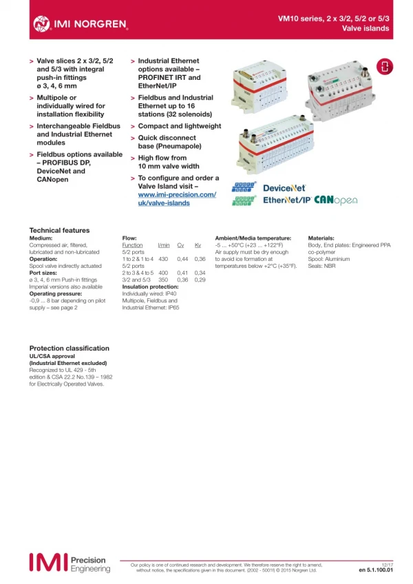
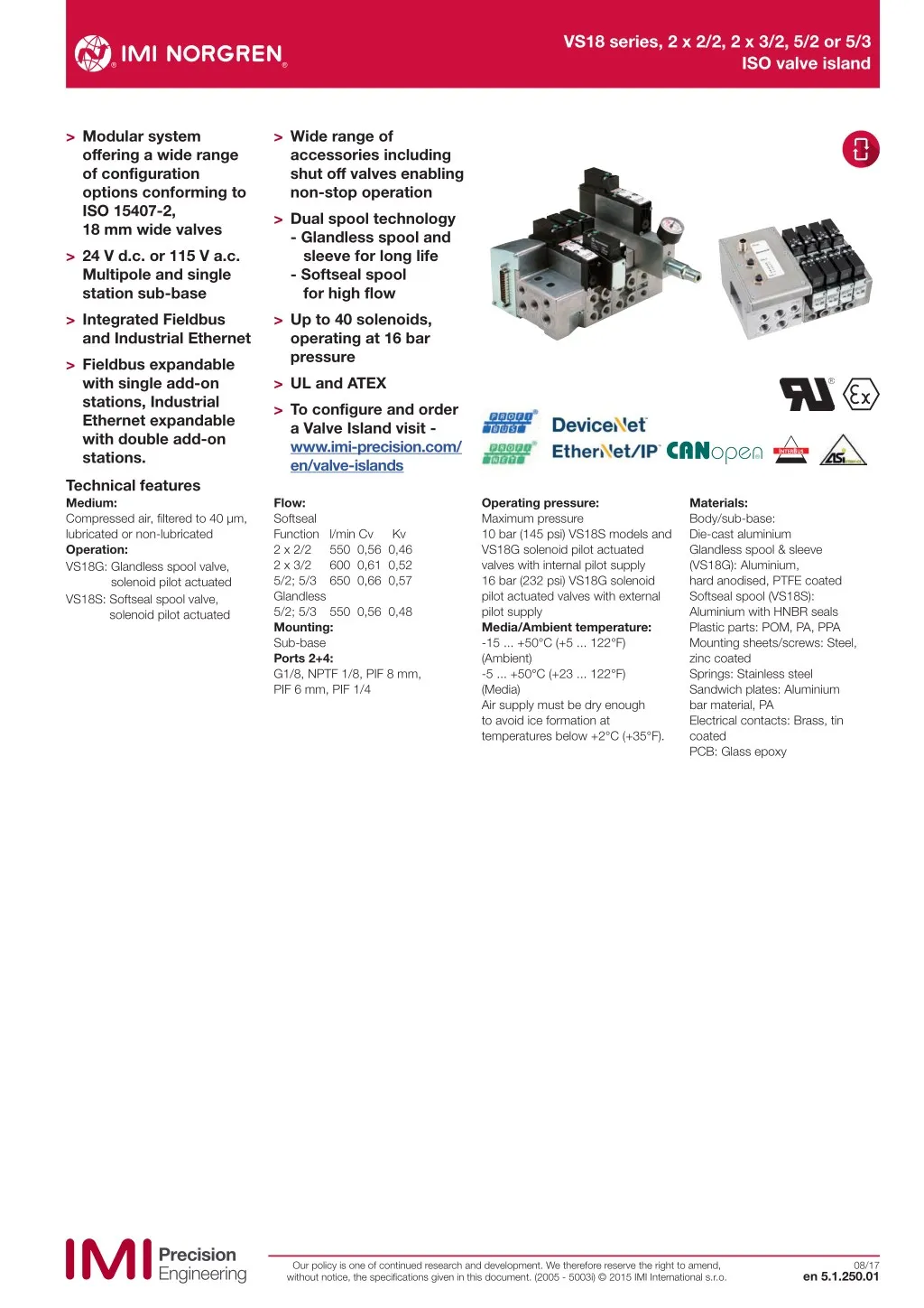
VS18 series, 2 x 2/2, 2 x 3/2, 5/2 or 5/3 ISO valve island > Modular system offering a wide range of configuration options conforming to ISO 15407-2, 18 mm wide valves > 24 V d.c. or 115 V a.c. Multipole and single station sub-base > Integrated Fieldbus and Industrial Ethernet > Fieldbus expandable with single add-on stations, Industrial Ethernet expandable with double add-on stations. > Wide range of accessories including shut off valves enabling non-stop operation > Dual spool technology - Glandless spool and sleeve for long life - Softseal spool for high flow > Up to 40 solenoids, operating at 16 bar pressure > UL and ATEX > To configure and order a Valve Island visit - www.imi-precision.com/ en/valve-islands Technical features Medium: Compressed air, filtered to 40 µm, lubricated or non-lubricated Operation: VS18G: Glandless spool valve, solenoid pilot actuated VS18S: Softseal spool valve, solenoid pilot actuated Flow: Softseal Function l/min Cv Kv 2 x 2/2 550 0,56 0,46 2 x 3/2 600 0,61 0,52 5/2; 5/3 650 0,66 0,57 Glandless 5/2; 5/3 550 0,56 0,48 Mounting: Sub-base Ports 2+4: G1/8, NPTF 1/8, PIF 8 mm, PIF 6 mm, PIF 1/4 Operating pressure: Maximum pressure 10 bar (145 psi) VS18S models and VS18G solenoid pilot actuated valves with internal pilot supply 16 bar (232 psi) VS18G solenoid pilot actuated valves with external pilot supply Media/Ambient temperature: -15 ... +50°C (+5 ... 122°F) (Ambient) -5 ... +50°C (+23 ... 122°F) (Media) Air supply must be dry enough to avoid ice formation at temperatures below +2°C (+35°F). Materials: Body/sub-base: Die-cast aluminium Glandless spool & sleeve (VS18G): Aluminium, hard anodised, PTFE coated Softseal spool (VS18S): Aluminium with HNBR seals Plastic parts: POM, PA, PPA Mounting sheets/screws: Steel, zinc coated Springs: Stainless steel Sandwich plates: Aluminium bar material, PA Electrical contacts: Brass, tin coated PCB: Glass epoxy Our policy is one of continued research and development. We therefore reserve the right to amend, without notice, the specifications given in this document. (2005 - 5003i) © 2015 IMI International s.r.o. 08/17 en 5.1.250.01
VS18 series, 2 x 2/2, 2 x 3/2, 5/2 or 5/3 ISO valve island Technical data 2 x 2/2 Double solenoid actuated softseal valves (flow 550 l/min) Function 2 x 2/2 Actuation/ return Pilot supply Pilot pressure (bar) Operating pressure (bar) Manual override Voltage Model Symbol NC NC NC NC NC NC NC NC NC NC NC NC NO NO NO NO NO NO NO NO NO NO NO NO NO/NC NO/NC NO/NC NO/NC NO/NC NO/NC NO/NC NO/NC NO/NC NO/NC NO/NC NO/NC Sol/Spring Sol/Spring Sol/Spring Sol/Spring Sol/Spring Sol/Spring Sol/Spring Sol/Spring Sol/Spring Sol/Spring Sol/Spring Sol/Spring Sol/Spring Sol/Spring Sol/Spring Sol/Spring Sol/Spring Sol/Spring Sol/Spring Sol/Spring Sol/Spring Sol/Spring Sol/Spring Sol/Spring Sol/Spring Sol/Spring Sol/Spring Sol/Spring Sol/Spring Sol/Spring Sol/Spring Sol/Spring Sol/Spring Sol/Spring Sol/Spring Sol/Spring Internal Internal Internal Internal Internal Internal External External External External External External Internal Internal Internal Internal Internal Internal External External External External External External Internal Internal Internal Internal Internal Internal External External External External External External 2,5 ... 10*1) 2,5 ... 10*1) 2,5 ... 10*1) 2,5 ... 10*1) 2,5 ... 10*1) 2,5 ... 10*1) 1,7 + (0,5 x press. port1)*2) 1,7 + (0,5 x press. port1)*2) 1,7 + (0,5 x press. port1)*2) 1,7 + (0,5 x press. port1)*2) 1,7 + (0,5 x press. port1)*2) 1,7 + (0,5 x press. port1)*2) 2,5 ... 10*1) 2,5 ... 10*1) 2,5 ... 10*1) 2,5 ... 10*1) 2,5 ... 10*1) 2,5 ... 10*1) 1,7 + (0,5 x press. port1)*2) 1,7 + (0,5 x press. port1)*2) 1,7 + (0,5 x press. port1)*2) 1,7 + (0,5 x press. port1)*2) 1,7 + (0,5 x press. port1)*2) 1,7 + (0,5 x press. port1)*2) 2,5 ... 10*1) 2,5 ... 10*1) 2,5 ... 10*1) 2,5 ... 10*1) 2,5 ... 10*1) 2,5 ... 10*1) 1,7 + (0,5 x press. port1)*2) 1,7 + (0,5 x press. port1)*2) 1,7 + (0,5 x press. port1)*2) 1,7 + (0,5 x press. port1)*2) 1,7 + (0,5 x press. port1)*2) 1,7 + (0,5 x press. port1)*2) -0,9 ... 10 -0,9 ... 10 -0,9 ... 10 -0,9 ... 10 -0,9 ... 10 -0,9 ... 10 -0,9 ... 10 -0,9 ... 10 -0,9 ... 10 -0,9 ... 10 -0,9 ... 10 -0,9 ... 10 -0,9 ... 10 -0,9 ... 10 -0,9 ... 10 -0,9 ... 10 -0,9 ... 10 -0,9 ... 10 -0,9 ... 10 -0,9 ... 10 -0,9 ... 10 -0,9 ... 10 -0,9 ... 10 -0,9 ... 10 -0,9 ... 10 -0,9 ... 10 -0,9 ... 10 -0,9 ... 10 -0,9 ... 10 -0,9 ... 10 -0,9 ... 10 -0,9 ... 10 -0,9 ... 10 -0,9 ... 10 -0,9 ... 10 -0,9 ... 10 Push only Push only Push & turn Push & turn Extended, Push only Extended, Push only Push only Push only Push & turn Push & turn Extended, Push only Extended, Push only Push only Push only Push & turn Push & turn Extended, Push only Extended, Push only Push only Push only Push & turn Push & turn Extended, Push only Extended, Push only Push only Push only Push & turn Push & turn Extended, Push only Extended, Push only Push only Push only Push & turn Push & turn Extended, Push only Extended, Push only 24 V d.c. 1,2 W 115 V a.c. 1,5 VA 24 V d.c. 1,2 W 115 V a.c. 1,5 VA 24 V d.c. 1,2 W 115 V a.c. 1,5 VA 24 V d.c. 1,2 W 115 V a.c. 1,5 VA 24 V d.c. 1,2 W 115 V a.c. 1,5 VA 24 V d.c. 1,2 W 115 V a.c. 1,5 VA 24 V d.c. 1,2 W 115 V a.c. 1,5 VA 24 V d.c. 1,2 W 115 V a.c. 1,5 VA 24 V d.c. 1,2 W 115 V a.c. 1,5 VA 24 V d.c. 1,2 W 115 V a.c. 1,5 VA 24 V d.c. 1,2 W 115 V a.c. 1,5 VA 24 V d.c. 1,2 W 115 V a.c. 1,5 VA 24 V d.c. 1,2 W 115 V a.c. 1,5 VA 24 V d.c. 1,2 W 115 V a.c. 1,5 VA 24 V d.c. 1,2 W 115 V a.c. 1,5 VA 24 V d.c. 1,2 W 115 V a.c. 1,5 VA 24 V d.c. 1,2 W 115 V a.c. 1,5 VA 24 V d.c. 1,2 W 115 V a.c. 1,5 VA VS18SE11DF313A VS18SE11DF318A VS18SE11DF213A VS18SE11DF218A VS18SE11DF513A VS18SE11DF518A VS18SE22DF313A VS18SE22DF318A VS18SE22DF213A VS18SE22DF218A VS18SE22DF513A VS18SE22DF518A VS18SF11DF313A VS18SF11DF318A VS18SF11DF213A VS18SF11DF218A VS18SF11DF513A VS18SF11DF518A VS18SF22DF313A VS18SF22DF318A VS18SF22DF213A VS18SF22DF218A VS18SF22DF513A VS18SF22DF518A VS18SG11DF313A VS18SG11DF318A VS18SG11DF213A VS18SG11DF218A VS18SG11DF513A VS18SG11DF518A VS18SG22DF313A VS18SG22DF318A VS18SG22DF213A VS18SG22DF218A VS18SG22DF513A VS18SG22DF518A 4 2 54 32 50 30 5 1 3 84 82 4 2 54 32 50 30 5 1 3 84 14 82 4 2 50 30 54 32 5 1 3 84 82 4 2 50 30 54 32 5 1 3 84 14 82 4 2 54 30 50 32 5 1 3 84 82 4 2 54 30 50 32 5 1 3 84 14 82 Valve dimensions see page 8 NO = Normally open, NC = Normally closed *1) Pilot air supply through port 1 *2) Pilot air supply through port 12/14 Our policy is one of continued research and development. We therefore reserve the right to amend, without notice, the specifications given in this document. (2005 - 5003i) © 2015 IMI International s.r.o. en 5.1.250.02 08/17
VS18 series, 2 x 2/2, 2 x 3/2, 5/2 or 5/3 ISO valve island 2 x 3/2 Double solenoid actuated softseal valves (flow 600 l/min) Function 2 x 3/2 Actuation/ return Pilot supply Pilot pressure (bar) Operating pressure (bar) Manual override Voltage Model Symbol NC NC NC NC NC NC NC NC NC NC NC NC NO NO NO NO NO NO NO NO NO NO NO NO NO/NC NO/NC NO/NC NO/NC NO/NC NO/NC NO/NC NO/NC NO/NC NO/NC NO/NC NO/NC Sol/Spring Sol/Spring Sol/Spring Sol/Spring Sol/Spring Sol/Spring Sol/Spring Sol/Spring Sol/Spring Sol/Spring Sol/Spring Sol/Spring Sol/Spring Sol/Spring Sol/Spring Sol/Spring Sol/Spring Sol/Spring Sol/Spring Sol/Spring Sol/Spring Sol/Spring Sol/Spring Sol/Spring Sol/Spring Sol/Spring Sol/Spring Sol/Spring Sol/Spring Sol/Spring Sol/Spring Sol/Spring Sol/Spring Sol/Spring Sol/Spring Sol/Spring Internal Internal Internal Internal Internal Internal External External External External External External Internal Internal Internal Internal Internal Internal External External External External External External Internal Internal Internal Internal Internal Internal External External External External External External – – – – – – 1,7 + (0,35 x op. press.) 1,7 + (0,35 x op. press.) 1,7 + (0,35 x op. press.) 1,7 + (0,35 x op. press.) 1,7 + (0,35 x op. press.) 1,7 + (0,35 x op. press.) – – – – – – 1,7 + (0,35 x op. press.) 1,7 + (0,35 x op. press.) 1,7 + (0,35 x op. press.) 1,7 + (0,35 x op. press.) 1,7 + (0,35 x op. press.) 1,7 + (0,35 x op. press.) – – – – – – 1,7 + (0,35 x op. press.) 1,7 + (0,35 x op. press.) 1,7 + (0,35 x op. press.) 1,7 + (0,35 x op. press.) 1,7 + (0,35 x op. press.) 1,7 + (0,35 x op. press.) 2,5 ... 10 2,5 ... 10 2,5 ... 10 2,5 ... 10 2,5 ... 10 2,5 ... 10 0 ... 10 0 ... 10 0 ... 10 0 ... 10 0 ... 10 0 ... 10 2,5 ... 10 2,5 ... 10 2,5 ... 10 2,5 ... 10 2,5 ... 10 2,5 ... 10 0 ... 10 0 ... 10 0 ... 10 0 ... 10 0 ... 10 0 ... 10 2,5 ... 10 2,5 ... 10 2,5 ... 10 2,5 ... 10 2,5 ... 10 2,5 ... 10 0 ... 10 0 ... 10 0 ... 10 0 ... 10 0 ... 10 0 ... 10 Push only Push only Push & turn Push & turn Extended, Push only Extended, Push only Push only Push only Push & turn Push & turn Extended, Push only Extended, Push only Push only Push only Push & turn Push & turn Extended, Push only Extended, Push only Push only Push only Push & turn Push & turn Extended, Push only Extended, Push only Push only Push only Push & turn Push & turn Extended, Push only Extended, Push only Push only Push only Push & turn Push & turn Extended, Push only Extended, Push only 24 V d.c. 1,2 W 115 V a.c. 1,5 VA 24 V d.c. 1,2 W 115 V a.c. 1,5 VA 24 V d.c. 1,2 W 115 V a.c. 1,5 VA 24 V d.c. 1,2 W 115 V a.c. 1,5 VA 24 V d.c. 1,2 W 115 V a.c. 1,5 VA 24 V d.c. 1,2 W 115 V a.c. 1,5 VA 24 V d.c. 1,2 W 115 V a.c. 1,5 VA 24 V d.c. 1,2 W 115 V a.c. 1,5 VA 24 V d.c. 1,2 W 115 V a.c. 1,5 VA 24 V d.c. 1,2 W 115 V a.c. 1,5 VA 24 V d.c. 1,2 W 115 V a.c. 1,5 VA 24 V d.c. 1,2 W 115 V a.c. 1,5 VA 24 V d.c. 1,2 W 115 V a.c. 1,5 VA 24 V d.c. 1,2 W 115 V a.c. 1,5 VA 24 V d.c. 1,2 W 115 V a.c. 1,5 VA 24 V d.c. 1,2 W 115 V a.c. 1,5 VA 24 V d.c. 1,2 W 115 V a.c. 1,5 VA 24 V d.c. 1,2 W 115 V a.c. 1,5 VA VS18SA11DF313A VS18SA11DF318A VS18SA11DF213A VS18SA11DF218A VS18SA11DF513A VS18SA11DF518A VS18SA22DF313A VS18SA22DF318A VS18SA22DF213A VS18SA22DF218A VS18SA22DF513A VS18SA22DF518A VS18SB11DF313A VS18SB11DF318A VS18SB11DF213A VS18SB11DF218A VS18SB11DF513A VS18SB11DF518A VS18SB22DF313A VS18SB22DF318A VS18SB22DF213A VS18SB22DF218A VS18SB22DF513A VS18SB22DF518A VS18SC11DF313A VS18SC11DF318A VS18SC11DF213A VS18SC11DF218A VS18SC11DF513A VS18SC11DF518A VS18SC22DF313A VS18SC22DF318A VS18SC22DF213A VS18SC22DF218A VS18SC22DF513A VS18SC22DF518A 4 2 14 12 10 10 84 5 1 3 82 4 2 14 12 10 10 8414 5 1 3 82 4 2 10 10 14 12 84 5 1 3 82 4 2 10 10 14 12 5 1 3 84 82 14 4 2 14 10 10 12 84 5 1 3 82 4 2 14 10 10 12 8414 5 1 3 82 Valve dimensions see page 8 NO = Normally open, NC = Normally closed Our policy is one of continued research and development. We therefore reserve the right to amend, without notice, the specifications given in this document. (2005 - 5003i) © 2015 IMI International s.r.o. en 5.1.250.03 08/17
VS18 series, 2 x 2/2, 2 x 3/2, 5/2 or 5/3 ISO valve island 5/2 Single and double solenoid actuated glandless valves (flow 550 l/min) Symbol Actuation/ return Pilot supply Pilot pressure (bar) Operating pressure (bar) Manual override Voltage Model Sol/Sol Sol/Sol Sol/Sol Sol/Sol Sol/Sol Sol/Sol Sol/Sol Sol/Sol Sol/Sol Sol/Sol Sol/Sol Sol/Sol Sol(Priority)/Sol Sol(Priority)/Sol Sol(Priority)/Sol Sol(Priority)/Sol Sol(Priority)/Sol Sol(Priority)/Sol Sol(Priority)/Sol Sol(Priority)/Sol Sol(Priority)/Sol Sol(Priority)/Sol Sol(Priority)/Sol Sol(Priority)/Sol Sol/Spring Sol/Spring Sol/Spring Sol/Spring Sol/Spring Sol/Spring Sol/Spring Sol/Spring Sol/Spring Sol/Spring Sol/Spring Sol/Spring Internal Internal Internal Internal Internal Internal External External External External External External Internal Internal Internal Internal Internal Internal External External External External External External Internal Internal Internal Internal Internal Internal External External External External External External – – – – – – 2 ... 10 2 ... 10 2 ... 10 2 ... 10 2 ... 10 2 ... 10 – – – – – – 2 ... 10 2 ... 10 2 ... 10 2 ... 10 2 ... 10 2 ... 10 – – – – – – 1,6 ... 10 1,6 ... 10 1,6 ... 10 1,6 ... 10 1,6 ... 10 1,6 ... 10 2 ... 10 2 ... 10 2 ... 10 2 ... 10 2 ... 10 2 ... 10 -0,9 ... 16 -0,9 ... 16 -0,9 ... 16 -0,9 ... 16 -0,9 ... 16 -0,9 ... 16 2 ... 10 2 ... 10 2 ... 10 2 ... 10 2 ... 10 2 ... 10 -0,9 ... 16 -0,9 ... 16 -0,9 ... 16 -0,9 ... 16 -0,9 ... 16 -0,9 ... 16 1,6 ... 10 1,6 ... 10 1,6 ... 10 1,6 ... 10 1,6 ... 10 1,6 ... 10 -0,9 ... 16 -0,9 ... 16 -0,9 ... 16 -0,9 ... 16 -0,9 ... 16 -0,9 ... 16 Push only Push only Push & turn Push & turn Extended, Push only Extended, Push only Push only Push only Push & turn Push & turn Extended, Push only Extended, Push only Push only Push only Push & turn Push & turn Extended, Push only Extended, Push only Push only Push only Push & turn Push & turn Extended, Push only Extended, Push only Push only Push only Push & turn Push & turn Extended, Push only Extended, Push only Push only Push only Push & turn Push & turn Extended, Push only Extended, Push only 24 V d.c. 1,2 W 115 V a.c. 1,5 VA 24 V d.c. 1,2 W 115 V a.c. 1,5 VA 24 V d.c. 1,2 W 115 V a.c. 1,5 VA 24 V d.c. 1,2 W 115 V a.c. 1,5 VA 24 V d.c. 1,2 W 115 V a.c. 1,5 VA 24 V d.c. 1,2 W 115 V a.c. 1,5 VA 24 V d.c. 1,2 W 115 V a.c. 1,5 VA 24 V d.c. 1,2 W 115 V a.c. 1,5 VA 24 V d.c. 1,2 W 115 V a.c. 1,5 VA 24 V d.c. 1,2 W 115 V a.c. 1,5 VA 24 V d.c. 1,2 W 115 V a.c. 1,5 VA 24 V d.c. 1,2 W 115 V a.c. 1,5 VA 24 V d.c. 1,2 W 115 V a.c. 1,5 VA 24 V d.c. 1,2 W 115 V a.c. 1,5 VA 24 V d.c. 1,2 W 115 V a.c. 1,5 VA 24 V d.c. 1,2 W 115 V a.c. 1,5 VA 24 V d.c. 1,2 W 115 V a.c. 1,5 VA 24 V d.c. 1,2 W 115 V a.c. 1,5 VA VS18G511DF313A VS18G511DF318A VS18G511DF213A VS18G511DF218A VS18G511DF513A VS18G511DF518A VS18G522DF313A VS18G522DF318A VS18G522DF213A VS18G522DF218A VS18G522DF513A VS18G522DF518A VS18G591DF313A VS18G591DF318A VS18G591DF213A VS18G591DF218A VS18G591DF513A VS18G591DF518A VS18G592DF313A VS18G592DF318A VS18G592DF213A VS18G592DF218A VS18G592DF513A VS18G592DF518A VS18G517DF313A VS18G517DF318A VS18G517DF213A VS18G517DF218A VS18G517DF513A VS18G517DF518A VS18G527DF313A VS18G527DF318A VS18G527DF213A VS18G527DF218A VS18G527DF513A VS18G527DF518A 14 12 4 2 84 5 1 3 82 4 2 14 12 5 3 84 82 14 1 14 12 4 2 84 5 1 3 82 4 2 14 12 5 3 82 84 14 1 4 2 14 12 84 5 3 1 2 4 12 14 5 3 84 14 1 Valve dimensions see page 8 Our policy is one of continued research and development. We therefore reserve the right to amend, without notice, the specifications given in this document. (2005 - 5003i) © 2015 IMI International s.r.o. en 5.1.250.04 08/17
VS18 series, 2 x 2/2, 2 x 3/2, 5/2 or 5/3 ISO valve island 5/2 Single and double solenoid actuated softseal valves (flow 650 l/min) Symbol Actuation/ return Pilot supply Pilot pressure (bar) Operating pressure (bar) Manual override Voltage Model Sol/Sol Sol/Sol Sol/Sol Sol/Sol Sol/Sol Sol/Sol Sol/Sol Sol/Sol Sol/Sol Sol/Sol Sol/Sol Sol/Sol Sol/Spring Sol/Spring Sol/Spring Sol/Spring Sol/Spring Sol/Spring Sol/Spring Sol/Spring Sol/Spring Sol/Spring Sol/Spring Sol/Spring Internal Internal Internal Internal Internal Internal External External External External External External Internal Internal Internal Internal Internal Internal External External External External External External – – – – – – 2 ... 10 2 ... 10 2 ... 10 2 ... 10 2 ... 10 2 ... 10 – – – – – – 2 ... 10 2 ... 10 2 ... 10 2 ... 10 2 ... 10 2 ... 10 2 ... 10 2 ... 10 2 ... 10 2 ... 10 2 ... 10 2 ... 10 -0,9 ... 10 -0,9 ... 10 -0,9 ... 10 -0,9 ... 10 -0,9 ... 10 -0,9 ... 10 2 ... 10 2 ... 10 2 ... 10 2 ... 10 2 ... 10 2 ... 10 -0,9 ... 10 -0,9 ... 10 -0,9 ... 10 -0,9 ... 10 -0,9 ... 10 -0,9 ... 10 Push only Push only Push & turn Push & turn Extended, Push only Extended, Push only Push only Push only Push & turn Push & turn Extended, Push only Extended, Push only Push only Push only Push & turn Push & turn Extended, Push only Extended, Push only Push only Push only Push & turn Push & turn Extended, Push only Extended, Push only 24 V d.c. 1,2 W 115 V a.c. 1,5 VA 24 V d.c. 1,2 W 115 V a.c. 1,5 VA 24 V d.c. 1,2 W 115 V a.c. 1,5 VA 24 V d.c. 1,2 W 115 V a.c. 1,5 VA 24 V d.c. 1,2 W 115 V a.c. 1,5 VA 24 V d.c. 1,2 W 115 V a.c. 1,5 VA 24 V d.c. 1,2 W 115 V a.c. 1,5 VA 24 V d.c. 1,2 W 115 V a.c. 1,5 VA 24 V d.c. 1,2 W 115 V a.c. 1,5 VA 24 V d.c. 1,2 W 115 V a.c. 1,5 VA 24 V d.c. 1,2 W 115 V a.c. 1,5 VA 24 V d.c. 1,2 W 115 V a.c. 1,5 VA VS18S511DF313A VS18S511DF318A VS18S511DF213A VS18S511DF218A VS18S511DF513A VS18S511DF518A VS18S522DF313A VS18S522DF318A VS18S522DF213A VS18S522DF218A VS18S522DF513A VS18S522DF518A VS18S517DF313A VS18S517DF318A VS18S517DF213A VS18S517DF218A VS18S517DF513A VS18S517DF518A VS18S527DF313A VS18S527DF318A VS18S527DF213A VS18S527DF218A VS18S527DF513A VS18S527DF518A 14 12 4 2 84 5 1 3 82 4 2 14 12 5 3 84 82 14 1 4 2 14 12 84 5 3 1 2 4 12 14 84 5 3 14 1 5/3 Double solenoid actuated glandless valves (flow 550 l/min) Symbol Function Actuation/ return Pilot supply Pilot pressure (bar) Operating pressure (bar) Manual override Voltage Model APB APB APB APB APB APB APB APB APB APB APB APB COE COE COE COE COE COE COE COE COE COE COE COE Sol/Sol Sol/Sol Sol/Sol Sol/Sol Sol/Sol Sol/Sol Sol/Sol Sol/Sol Sol/Sol Sol/Sol Sol/Sol Sol/Sol Sol/Sol Sol/Sol Sol/Sol Sol/Sol Sol/Sol Sol/Sol Sol/Sol Sol/Sol Sol/Sol Sol/Sol Sol/Sol Sol/Sol Internal Internal Internal Internal Internal Internal External External External External External External Internal Internal Internal Internal Internal Internal External External External External External External – – – – – – 2 ... 10 2 ... 10 2 ... 10 2 ... 10 2 ... 10 2 ... 10 – – – – – – 2 ... 10 2 ... 10 2 ... 10 2 ... 10 2 ... 10 2 ... 10 2 ... 10 2 ... 10 2 ... 10 2 ... 10 2 ... 10 2 ... 10 -0,9 ... 16 -0,9 ... 16 -0,9 ... 16 -0,9 ... 16 -0,9 ... 16 -0,9 ... 16 2 ... 10 2 ... 10 2 ... 10 2 ... 10 2 ... 10 2 ... 10 -0,9 ... 16 -0,9 ... 16 -0,9 ... 16 -0,9 ... 16 -0,9 ... 16 -0,9 ... 16 Push only Push only Push & turn Push & turn Extended, Push only Extended, Push only Push only Push only Push & turn Push & turn Extended, Push only Extended, Push only Push only Push only Push & turn Push & turn Extended, Push only Extended, Push only Push only Push only Push & turn Push & turn Extended, Push only Extended, Push only 24 V d.c. 1,2 W 115 V a.c. 1,5 VA 24 V d.c. 1,2 W 115 V a.c. 1,5 VA 24 V d.c. 1,2 W 115 V a.c. 1,5 VA 24 V d.c. 1,2 W 115 V a.c. 1,5 VA 24 V d.c. 1,2 W 115 V a.c. 1,5 VA 24 V d.c. 1,2 W 115 V a.c. 1,5 VA 24 V d.c. 1,2 W 115 V a.c. 1,5 VA 24 V d.c. 1,2 W 115 V a.c. 1,5 VA 24 V d.c. 1,2 W 115 V a.c. 1,5 VA 24 V d.c. 1,2 W 115 V a.c. 1,5 VA 24 V d.c. 1,2 W 115 V a.c. 1,5 VA 24 V d.c. 1,2 W 115 V a.c. 1,5 VA VS18G611DF313A VS18G611DF318A VS18G611DF213A VS18G611DF218A VS18G611DF513A VS18G611DF518A VS18G622DF313A VS18G622DF318A VS18G622DF213A VS18G622DF218A VS18G622DF513A VS18G622DF518A VS18G711DF313A VS18G711DF318A VS18G711DF213A VS18G711DF218A VS18G711DF513A VS18G711DF518A VS18G722DF313A VS18G722DF318A VS18G722DF213A VS18G722DF218A VS18G722DF513A VS18G722DF518A 4 2 12 14 84 5 3 82 1 4 2 12 14 84 5 3 82 14 1 4 2 12 14 84 5 3 82 1 4 2 12 14 84 5 3 82 14 1 Valve dimensions see page 8 APB = All Ports BlockedCOE= Centre Open Exhaust Our policy is one of continued research and development. We therefore reserve the right to amend, without notice, the specifications given in this document. (2005 - 5003i) © 2015 IMI International s.r.o. en 5.1.250.05 08/17
VS18 series, 2 x 2/2, 2 x 3/2, 5/2 or 5/3 ISO valve island 5/3 Double solenoid actuated Softseal valves (flow 650 l/min) Function Actuation/ return Pilot supply Pilot pressure (bar) Operating pressure (bar) Manual override Voltage Model Symbol APB APB APB APB APB APB APB APB APB APB APB APB COE COE COE COE COE COE COE COE COE COE COE COE Sol/Sol Sol/Sol Sol/Sol Sol/Sol Sol/Sol Sol/Sol Sol/Sol Sol/Sol Sol/Sol Sol/Sol Sol/Sol Sol/Sol Sol/Sol Sol/Sol Sol/Sol Sol/Sol Sol/Sol Sol/Sol Sol/Sol Sol/Sol Sol/Sol Sol/Sol Sol/Sol Sol/Sol Internal Internal Internal Internal Internal Internal External External External External External External Internal Internal Internal Internal Internal Internal External External External External External External – – – – – – 2 ... 10 2 ... 10 2 ... 10 2 ... 10 2 ... 10 2 ... 10 – – – – – – 2,5 ... 10 2,5 ... 10 2,5 ... 10 2,5 ... 10 2,5 ... 10 2,5 ... 10 2 ... 10 2 ... 10 2 ... 10 2 ... 10 2 ... 10 2 ... 10 -0,9 ... 10 -0,9 ... 10 -0,9 ... 10 -0,9 ... 10 -0,9 ... 10 -0,9 ... 10 2,5 ... 10 2,5 ... 10 2,5 ... 10 2,5 ... 10 2,5 ... 10 2,5 ... 10 -0,9 ... 10 -0,9 ... 10 -0,9 ... 10 -0,9 ... 10 -0,9 ... 10 -0,9 ... 10 Push only Push only Push & turn Push & turn Extended, Push only Extended, Push only Push only Push only Push & turn Push & turn Extended, Push only Extended, Push only Push only Push only Push & turn Push & turn Extended, Push only Extended, Push only Push only Push only Push & turn Push & turn Extended, Push only Extended, Push only 24 V d.c. 1,2 W 115 V a.c. 1,5 VA 24 V d.c. 1,2 W 115 V a.c. 1,5 VA 24 V d.c. 1,2 W 115 V a.c. 1,5 VA 24 V d.c. 1,2 W 115 V a.c. 1,5 VA 24 V c.c. 1,2 W 115 V a.c. 1,5 VA 24 V d.c. 1,2 W 115 V a.c. 1,5 VA 24 V d.c. 1,2 W 115 V a.c. 1,5 VA 24 V d.c. 1,2 W 115 V a.c. 1,5 VA 24 V d.c. 1,2 W 115 V a.c. 1,5 VA 24 V d.c. 1,2 W 115 V a.c. 1,5 VA 24 V d.c. 1,2 W 115 V a.c. 1,5 VA 24 V d.c. 1,2 W 115 V a.c. 1,5 VA VS18S611DF313A VS18S611DF318A VS18S611DF213A VS18S611DF218A VS18S611DF513A VS18S611DF518A VS18S622DF313A VS18S622DF318A VS18S622DF213A VS18S622DF218A VS18S622DF513A VS18S622DF518A VS18S711DF313A VS18S711DF318A VS18S711DF213A VS18S711DF218A VS18S711DF513A VS18S711DF518A VS18S722DF313A VS18S722DF318A VS18S722DF213A VS18S722DF218A VS18S722DF513A VS18S722DF518A 4 2 12 14 84 5 3 82 1 4 2 12 14 5 3 82 84 14 1 4 2 12 14 84 5 3 82 1 4 2 12 14 84 5 3 82 14 1 Valve dimensions see page 8 APB = All Ports BlockedCOE= Centre Open Exhaust VS18˙˙˙˙DF˙˙˙˙ Options selector for valve slices Spool technology Glandless spool & sleeve Softseal spool Guiding systems 2 x 3/2 NC *3) 2 x 3/2 NO *3) 2 x 3/2 NO/NC *3) 2 x 2/2 NC *3) 2 x 2/2 NO *3) 2 x 2/2 NO/NC *3) 5/2 5/3 APB 5/3 COE Substitute Application Standard environment ATEX approval *6) Voltage 24 V d.c 1,2 W (±10%) 115 V a.c 1,5 VA (-10/+15%) Substitute G S A E Substitute Substitute A B C E F G 5 6 7 13 18 on request 12 V d.c. 1,2 W (±10%) on request 12 V d.c. 1,5 W (-17/+20%) on request 24 V d.c 1,5 W (-17/+20%) Manual override *5) Push & turn Push only Extended, Push only Actuation/Pilot supply Solenoid/Spring Internal pilot supply Substitute 2 3 5 *3) Available with softseal spool only (VS18S). Substitute 17 27 Solenoid/Spring External pilot supply 11 Solenoid/Solenoid Internal pilot supply 22 Solenoid/Solenoid External pilot supply 91 Solenoid priority side 14/Solenoid (5/2 only) Internal pilot supply *4) 92 Solenoid priority side 14/Solenoid (5/2 only) External pilot supply *4) *4) Available with glandless spool & sleeve only (VS18G) *5) Option “without manual override” available on request. *6) Available with 24 V d.c. 1,2 W (±10%) only Our policy is one of continued research and development. We therefore reserve the right to amend, without notice, the specifications given in this document. (2005 - 5003i) © 2015 IMI International s.r.o. en 5.1.250.06 08/17
VS18 series, 2 x 2/2, 2 x 3/2, 5/2 or 5/3 ISO valve island Electrical details for solenoid operators Protection classification (IP Code): All VS18 valve islands fulfill IP65 and NEMA4 ratings. Power supply and precautions: AII VS18 24 V d.c products are designed to be used with a protective extra low voltage (PELV) power supply. All VS18 115 V a.c products correspond to the protection class I. Connection of the protective earth (PE) ground is required. UL approval: Recognized to UL 429 for Electrically Operated Valves (not applicable for Industrial Ethernet options). ATEX: The 24 V d.c Multipole and Fieldbus valve islands fulfils the requirement of the standard 2014/34/EU for intended use in hazardous locations. Voltage tolerances Voltage tolerances Rating Inlet orifice Indication Surge surpression Materials (24 V d.c) +/- 10% (115 V a.c) -10%/+15% 100 % Continuous duty 0,8 mm LED green Transil diode PPS (body), FKM and NBR (seal) Multipole and Industrial Ethernet versions: II 3G Ex nA IIC T4 Gc II 3D Ex tc IIIC T135°C Dc Fieldbus versions: II 3G Ex nA IIC T4 Gc II 3D Ex tc IIIB T135°C Dc Note: Alternative voltage and voltage tolerances see option selector on page 6 Equipment group, category, type of protection: The Declaration of Conformity of the valve islands was conducted by IMI Precision Engineering Norgren GmbH, D-70731 Fellbach. Please review all ATEX data and notes in the maintenance and instruction booklet to eliminate any risks, allowing for safe function of the valve islands. Accessories DIN EN 50 022 rail (1 m) DIN-rail mounting kit Blanking disc to Manual override set-up kit Spare valve identification labels *7) Blanking plug for base connector hole *8) modular sub-base Electrical Connection Multipole, Fieldbus and Industrial Ethernet V10009-C00 (35 x 7,5 mm) V70531-KA0 *9) VS1872405-KF00 (Ports 1, 3, 5) VS2672906-KG00 VS2672905-KG00 (10 pcs.) VS2672914-KG00 VS1872406-KF00 (Port 12/14) Industrial Ethernet (only) *7) When purchasing assembled valve islands from IMI Norgren, valve identification labels are already included. *8) When V40/V41 valves are fitted on VS18 bases. *9) Not suitable for Industrial Ethernet VS2672971-KG00 Base accessories Intermediate supply/ exhaust module Blanking plate Electrical Connection Page 14 Page 14 Multipole, Fieldbus and Industrial Ethernet VS1872402-AF00 (G1/8) VS1872402-PF00 (NPTF 1/8) VS1872404-KF00 *9) Industrial Ethernet (only) VS1872407-KF00 Sandwich plates Single pressure regulator plate Double pressure regulator plate Flow regulator plate Sandwich plate with additional pressure port 1 Single valve shut-off plate Page 12 Page 12 Page 13 Page 13 Page 14 VS1872400-KF10 (Port 1) VS1872400-KF20 (Port 2) VS1872400-KF30 (Port 4) VS1872400-KF40 (Ports 2+4) VS1872401-KF00 (Ports 3+5) VS1872428-KFG00 (G1/8) VS1872403-KF00 (Port 1) Sub-bases and end plates Single station sub-base Double station modular sub-base Single station modular sub-base End plate kit Page 9 Page 25 and 28 Page 25 Page 25 Our policy is one of continued research and development. We therefore reserve the right to amend, without notice, the specifications given in this document. (2005 - 5003i) © 2015 IMI International s.r.o. en 5.1.250.07 08/17
VS18 series, 2 x 2/2, 2 x 3/2, 5/2 or 5/3 ISO valve island Valve dimensions VS18*5*7DF*1** 5/2 Single solenoid pilot valve, mechanical spring return Dimensions in mm Projection/First angle VS18****DF*1** 2 x 2/2, 2 x 3/2, 5/2 and 5/3 Double solenoid, pilot valve 1 1 1 1 52,5 52,5 52,5 52,5 37,5 37,5 37,5 37,5 5,5 5,5 5,5 5,5 8 8 8 8 M 3 M 3 M 3 M 3 41 41 101 101 120 120 19 19 19 19 12,5 12,5 12,5 12,5 1 Manual override Our policy is one of continued research and development. We therefore reserve the right to amend, without notice, the specifications given in this document. (2005 - 5003i) © 2015 IMI International s.r.o. en 5.1.250.08 08/17
VS18 series, 2 x 2/2, 2 x 3/2, 5/2 or 5/3 ISO valve island Single station sub-base Description Ports 1, 3 & 5 G1/8 NPTF 1/8 NPTF 1/8 Ports 12/14 & 82/84 G1/8 NPTF 1/8 NPTF 1/8 Ports 2 & 4 G1/8 NPTF 1/8 NPTF 1/8 Connector type M12 M12 NPTF1/2 conduit Model Single station sub-base for 24 V d.c. Single station sub-base for 24 V d.c. Single station sub-base for 24 V d.c. and 115 V a.c. VS1872010-AF00 VS1872010-PF00 VS1872011-PF00 Connector type: NPTF 1/2 conduit with flying leads Dimensions in mm Projection/First angle A A 85,5 85,5 2 2 3 3 5 5 33 33 24,5 24,5 24,5 24,5 12/14 12/14 23 23 16 16 1 1 16 16 15 15 14 14 82/84 82/84 4 4 62 62 1/2 NPTF 1/2 NPTF 77 77 30 30 92 92 55 55 69,5 69,5 112 112 139 139 84 84 A A 98 98 60 60 48,5 48,5 4 4 Wiring information 34,5 34,5 42 42 Wire colour Green Yellow Black Red Function Earth Signal for solenoid 12 Common for solenoid 12 and 14 Signal for solenoid 14 Connector type: M12 A A 85,5 85,5 2 2 3 3 5 5 33 33 24,5 24,5 24,5 24,5 12/14 12/14 23 23 1 1 16 16 14 14 15 15 14 14 82/84 82/84 4 4 M 12 M 12 49,5 49,5 17,5 17,5 64,5 64,5 42,5 42,5 79,5 79,5 99,5 99,5 57 57 71,5 71,5 126,5 126,5 85,5 85,5 A A 36 36 60 60 4,5 4,5 17 17 4 4 34,5 34,5 Pin assignment (conforming to DIN ISO 20401) 42 42 Male Pin no. 1 2 3 4 Function Not used Signal for solenoid 12 Common for solenoid 12 and 14 Signal for solenoid 14 3 4 2 1 Our policy is one of continued research and development. We therefore reserve the right to amend, without notice, the specifications given in this document. (2005 - 5003i) © 2015 IMI International s.r.o. en 5.1.250.09 08/17
VS18 series, 2 x 2/2, 2 x 3/2, 5/2 or 5/3 ISO valve island Valve island dimensions - Multipole and Fieldbus See page 24 and 25 for sub-base and end plate kit ordering information Dimensions in mm Projection/First angle 92,5 60,5 52,5 96,5 81,5 21,5 38 28 20 9,5 53 19 11,5 3 72,5 92 109 111 113,5 132,5 14,5 25 Dimensions for surface mounting: Slot length = 4,3mm (max. M4 screws). Clamp length = 35,7mm. Note: Never plug port 82/84. Plugging this port will cause valves to malfunction. 2 N x 19 40 44 14,5 N Number of stations 2 62,5 19,5 Electrical connection Min. no. of valve stations Multipole 2 AS-Interface 2 Other Fieldbus protocols 4 Max. no. of valve stations 20 6 16 For details see page 16 22 19 Our policy is one of continued research and development. We therefore reserve the right to amend, without notice, the specifications given in this document. (2005 - 5003i) © 2015 IMI International s.r.o. en 5.1.250.10 08/17
VS18 series, 2 x 2/2, 2 x 3/2, 5/2 or 5/3 ISO valve island Valve island dimensions - Industrial Ethernet See page 28 for sub-base and end plate kit ordering information Dimensions in mm Projection/First angle 96,4 12/14 1 82/84 2 2 21,4 36,5 35 4 4 3 5 16 13 9,35 19,1 11,4 23 60,5 21,75 44 47 108,9 130,1 65 19,5 62,65 9 14,5 25 N x 19 79,5 N Number of stations Electrical connection Min. no. of valve stations Industrial Ethernet protocols 4 Max. no. of valve stations 20 For details see page 20 and 21 Our policy is one of continued research and development. We therefore reserve the right to amend, without notice, the specifications given in this document. (2005 - 5003i) © 2015 IMI International s.r.o. en 5.1.250.11 08/17
VS18 series, 2 x 2/2, 2 x 3/2, 5/2 or 5/3 ISO valve island Sandwich plates Pressure regulator sandwich plates Symbol Model VS1872400-KF10 Description Regulation of port 1, regulator on side 12 Symbol Model VS1872400-KF30 Description Regulation of port 4, regulator on side 14 14 5 4 1 2 3 12 14 5 4 1 2 3 12 VS1872400-KF20 Regulation of port 2, regulator on side 12 VS1872400-KF40 Regulation of ports 2+4 14 5 4 1 2 3 12 14 5 4 1 2 3 12 Dimensions in mm Projection/First angle Flow characteristics for pressure regulator plates bar 8 96,5 Regulated pressure (bar) 95 6 39,5 4 143 2 0 50 100 150 200 250 300 350 qn l / min 72 4 3 1 Regulation of port 1 2 Regulation of port 2 3 Regulation of port 4 4 Regulation of port 2+4 5 Gauge 258 186,5 1 77,5 77,5 2 5 Spare part number for gauge: V70534-500 Our policy is one of continued research and development. We therefore reserve the right to amend, without notice, the specifications given in this document. (2005 - 5003i) © 2015 IMI International s.r.o. en 5.1.250.12 08/17
VS18 series, 2 x 2/2, 2 x 3/2, 5/2 or 5/3 ISO valve island Sandwich plates Flow regulator & additional pressure Symbol Model VS1872428-KF00 Description Sandwich plate with additional pressure port 1 (G1/8), supplied with gasket Symbol Model VS1872401-KF00 Description Flow regulator supplied with gasket, dual regulation of exhaust ports 3 and 5 2 4 2 4 VS1872429-KF00 Sandwich plate with additional pressure port 1 (NPTF 1/8), supplied with gasket 1 1e 5 3 5 3 1 Dimensions in mm Projection/First angle 9,5 1 2 15,5 15,5 114 114 1 1 54,5 120,5 1 Flow regulator plate 2 Sandwich plate with additional pressure port 1 Flow characteristics Dual regulation of exhaust ports 3 and 5 600 550 500 450 Exhaust flow (ports 3 + 5) 400 Port 3 350 300 250 200 Port 5 150 100 50 0 0 1 2 3 4 Number of turns from close 5 6 7 8 9 10 11 12 Flow: Port 1>2 and 1>4: remains unchanged. Flow measured at 6 bar inlet, pressure drop 1 bar Our policy is one of continued research and development. We therefore reserve the right to amend, without notice, the specifications given in this document. (2005 - 5003i) © 2015 IMI International s.r.o. en 5.1.250.13 08/17
VS18 series, 2 x 2/2, 2 x 3/2, 5/2 or 5/3 ISO valve island Sandwich plates–Single valve shut-off plate Base accessories Model VS1872402-AF00 VS1872402-PF00 VS1872404-KF00 Description Intermediate supply/exhaust module, port size G1/8 *9) Intermediate supply/exhaust module, port size NPTF 1/8 *9) Blanking plate for blocking of unused stations (supplied with gasket) Symbol Model VS1872403-KF00 Description Single valve shut-off plate supplied with gasket 4 2 *9) for use see page 15 1 3 5 Allows individual exchange of valve while valve island is pressurised by port 1 - enabling unbroken production in a continuously operating process. Flow restricted to max. 240 l/min. Dimensions in mm Projection/First angle 1 1 15,5 16 20 114 98,5 3 2 9,5 8 43 65 120,5 80 1 Single valve shut-off plate 2 Intermediate supply/exhaust module 3 Blanking plate Our policy is one of continued research and development. We therefore reserve the right to amend, without notice, the specifications given in this document. (2005 - 5003i) © 2015 IMI International s.r.o. en 5.1.250.14 08/17
VS18 series, 2 x 2/2, 2 x 3/2, 5/2 or 5/3 ISO valve island Multi pressure configurations A B Blanking disc VS1872405-KF00 Type Suitable for ports 1, 3 and/or 5 Intermediate supply/exhaust module Type VS1872402-AF00 VS1872402-PF00 G1/8 NPTF 1/8 Dual pressure Dimensions in mm Projection/First angle Pressure 1 Pressure 2 A Multi pressure Pressure 3 Pressure 4 Pressure 1 Pressure 2 AB A B A B A Our policy is one of continued research and development. We therefore reserve the right to amend, without notice, the specifications given in this document. (2005 - 5003i) © 2015 IMI International s.r.o. en 5.1.250.15 08/17
VS18 series, 2 x 2/2, 2 x 3/2, 5/2 or 5/3 ISO valve island Multipole options Connector type D-Sub 9-pin D-Sub 15-pin D-Sub 25-pin D-Sub 44-pin M23 19-pin NPTF1 Conduit entry with terminals Voltage 24 V d.c. 24 V d.c. 24 V d.c. 24 V d.c. 115 V a.c., 24 V d.c. 115 V a.c., 24 V d.c. No. of stations 02/03/04 02/03/04/05/06/07 02/03/04/05/06/07/08/09/10/11/12 08/09/10/11/12/13/14/15/16/17/18/19/20 02/03/04/05/06/07/08 02/03/04/05/06/07/08/09/10/11/12 Max. no. solenoids 8 14 24 40 16 24 For valve islands with 17 ... 20 valve stations, please contact our customer service. For details of single parts see pages 26 and 27. D-Sub 9-pin D-Sub 15-pin Dimensions in mm Projection/First angle 4,5 4,5 25 33,5 21 17 26 26 D-Sub 25- / 44 -pin M23 19-pin 22,5 4,5 M23 47 54 10 26 25 NPTF1 Conduit entry with terminals 1 36 47,5 21,5 1 Maximum wire size AWG18 Our policy is one of continued research and development. We therefore reserve the right to amend, without notice, the specifications given in this document. (2005 - 5003i) © 2015 IMI International s.r.o. en 5.1.250.16 08/17
VS18 series, 2 x 2/2, 2 x 3/2, 5/2 or 5/3 ISO valve island Multipole accessories Cable length IP65 *10) D-Sub connector 9-pin D-Sub connector 15-pin IP65 *10) D-Sub connector 25-pin IP65 *10) D-Sub connector 44-pin IP65 *10) M23 connector 19-pin IP65 *10) 1 m 3 m 5 m *10) Required for ATEX For cable length longer than 5 m please contact customer service. VS2672910-KG00 VS2672911-KG00 VS2672912-KG00 VS2672915-KG00 VS2672916-KG00 VS2672917-KG00 V11569-E01 V11569-E03 V11569-E05 V11570-E01 V11570-E03 V11570-E05 VS2672943-KG00 VS2672944-KG00 VS2672945-KG00 D-Sub connector 9-pin *11) Pin no. Wire colour 1 White 2 Brown 3 Green 4 Yellow 5 Grey 6 Pink 7 Blue 8 Red 9 Black D-Sub connector 25-pin *11) Pin no. Wire colour 1 White 2 Brown 3 Green 4 Yellow 5 Grey 6 Pink 7 Blue 8 Red 9 Black 10 Violet 11 Grey/Pink 12 Red/Blue 13 White/Green 14 Brown/Green 15 White/Yellow 16 Yellow/Brown 17 White/Grey 18 Grey/Brown 19 White/Pink 20 Pink/Brown 21 White/Blue 22 Brown/Blue 23 White/Red 24 Brown/Red 25 White/Black Socket Solenoid 1-a Solenoid 2-a Solenoid 3-a Solenoid 4-a Solenoid 1-b Solenoid 2-b Solenoid 3-b Solenoid 4-b Common Pilot 14 14 14 14 12 12 12 12 – Station 1 2 3 4 1 2 3 4 – Socket Solenoid Solenoid Solenoid Solenoid Solenoid Solenoid Solenoid Solenoid Solenoid Solenoid Solenoid Solenoid Common Solenoid Solenoid Solenoid Solenoid Solenoid Solenoid Solenoid Solenoid Solenoid Solenoid Solenoid Solenoid Pilot 14 14 14 14 14 14 14 14 14 14 14 14 - 12 12 12 12 12 12 12 12 12 12 12 12 Station 1 2 3 4 5 6 7 8 9 10 11 12 - 1 2 3 4 5 6 7 8 9 10 11 12 1-a 2-a 3-a 4-a 5-a 6-a 7-a 8-a 9-a 10-a 11-a 12-a D-Sub connector 15-pin *11) Pin no. Wire colour 1 White 2 Brown 3 Green 4 Yellow 5 Grey 6 Pink 7 Blue 8 Red 9 Black 10 Violet 11 Grey/Pink 12 Red/Blue 13 White/Green 14 Brown/Green 15 White/Yellow *11) According to IEC60757 Socket Solenoid 1-a Solenoid 2-a Solenoid 3-a Solenoid 4-a Solenoid 5-a Solenoid 6-a Solenoid 7-a Solenoid 1-b Solenoid 2-b Solenoid 3-b Solenoid 4-b Solenoid 5-b Solenoid 6-b Solenoid 7-b Common Pilot 14 14 14 14 14 14 14 12 12 12 12 12 12 12 – Station 1 2 3 4 5 6 7 1 2 3 4 5 6 7 – 1-b 2-b 3-b 4-b 5-b 6-b 7-b 8-b 9-b 10-b 11-b 12-b Our policy is one of continued research and development. We therefore reserve the right to amend, without notice, the specifications given in this document. (2005 - 5003i) © 2015 IMI International s.r.o. en 5.1.250.17 08/17
VS18 series, 2 x 2/2, 2 x 3/2, 5/2 or 5/3 ISO valve island D-Sub connector 44-pin *11) M23 connector 19-pin Pin no. 1 2 3 4 5 6 7 8 9 10 11 12 13 14 15 16 17 18 19 20 21 22 23 24 25 26 27 28 29 30 31 32 33 34 35 36 37 38 39 40 41 42 43 44 Wire colour White Brown Green Yellow Grey Pink Blue Red Black Violet Grey/Pink Red/Blue White/Green Brown/Green White/Yellow Yellow/Brown White/Grey Grey/Brown White/Pink Pink/Brown White/Blue Brown/Blue White/Red Brown/Red White/Black Brown/Black Grey/Green Yellow/Grey Pink/Green Yellow/Pink Green/Blue Yellow/Blue – – – – – – – – – – Blue/Black *12) Red/Black *12) Socket Solenoid 1–a Solenoid 2–a Solenoid 3–a Solenoid 4–a Solenoid 5–a Solenoid 6–a Solenoid 7–a Solenoid 8–a Solenoid 9–a Solenoid 10–a Solenoid 11–a Solenoid 12–a Solenoid 13–a Solenoid 14–a Solenoid 15–a Solenoid 1–b Solenoid 2–b Solenoid 3–b Solenoid 4–b Solenoid 5–b Solenoid 6–b Solenoid 7–b Solenoid 8–b Solenoid 9–b Solenoid 10–b Solenoid 11–b Solenoid 12–b Solenoid 13–b Solenoid 14–b Solenoid 15–b Solenoid 16–a Solenoid 16–b Not used Not used Not used Not used Not used Not used Not used Not used Not used Not used Common Common Pilot 14 14 14 14 14 14 14 14 14 14 14 14 14 14 14 12 12 12 12 12 12 12 12 12 12 12 12 12 12 12 14 12 – – – – – – – – – – – – Station 1 2 3 4 5 6 7 8 9 10 11 12 13 14 15 1 2 3 4 5 6 7 8 9 10 11 12 13 14 15 16 16 – – – – – – – – – – – – Pin no. 1 2 3 4 5 6 7 8 9 10 11 12 13 14 15 16 17 18 19 Wire colour White Green/Brown Green Yellow Grey Blue(thick) White/Grey Red Black Violet Grey/Pink Yellow/Green White/Green Brown/Green White/Yellow Yellow/Brown Pink Red/Blue Brown(thick) Socket Solenoid 8-a Solenoid 6-a Solenoid 4-a Solenoid 2-b Solenoid 2-a Common Solenoid 1-b Solenoid 3-b Solenoid 5-b Solenoid 7-b Solenoid 7-a Earth Solenoid 6-b Solenoid 4-b Solenoid 1-a Solenoid 3-a Solenoid 5-a Solenoid 8-b Not used Pilot 14 14 14 12 14 – 12 12 12 12 14 – 12 12 14 14 14 12 – Station 8 6 4 2 2 – 1 3 5 7 7 – 6 4 1 3 5 8 – NPTF1 Conduit entry with terminals *13) Pin no. C1 C2 C3 C4 C5 C6 C7 C8 C9 C10 C11 C12 C13 C14 C15 C16 C17 C18 C19 C20 C21 C22 C23 C24 C25 C26 C27 C28 Socket Solenoid 1-a Solenoid 2-a Solenoid 3-a Solenoid 4-a Solenoid 5-a Solenoid 6-a Solenoid 7-a Solenoid 8-a Solenoid 9-a Solenoid 10-a Solenoid 11-a Solenoid 12-a Solenoid 1-b Solenoid 2-b Solenoid 3-b Solenoid 4-b Solenoid 5-b Solenoid 6-b Solenoid 7-b Solenoid 8-b Solenoid 9-b Solenoid 10-b Solenoid 11-b Solenoid 12-b Common Common Earth Earth Pilot 14 14 14 14 14 14 14 14 14 14 14 14 12 12 12 12 12 12 12 12 12 12 12 12 – – – – Station 1 2 3 4 5 6 7 8 9 10 11 12 1 2 3 4 5 6 7 8 9 10 11 12 – – – – *11) According to IEC60757 *12) The IMI Norgren D-Sub 44-pin cables (see part numbers on page 16) do not have 44 wires, but only 34 wires. Therefore, the wires associated with pins 1 through 32 are according to IEC60757, wires 43 and 44 differ from the standard and are coloured in green/black and yellow/black. *13) Max.wire size AWG18 Our policy is one of continued research and development. We therefore reserve the right to amend, without notice, the specifications given in this document. (2005 - 5003i) © 2015 IMI International s.r.o. en 5.1.250.18 08/17
VS18 series, 2 x 2/2, 2 x 3/2, 5/2 or 5/3 ISO valve island Fieldbus and Industrial Ethernet options: Overview Protocol Communications Connector Power connector No. of stations Max. no. solenoids PROFIBUS DP 1 x D-Sub; 9-pin 2 x M12; 5-pin 2 x M12; 5-pin 2 x M12; 4-pin 1 x M12; 5-pin 2 x M12; 4-pin 1 x M12; 5-pin 2 x D-Sub; 9-pin 1 x M12; 4-pin 1 x M12; 4-pin M12; 4-pin M12; 4-pin 7/8; 5-pin M12; 5-pin M12; 4-pin M12; 5-pin M12; 4-pin M12; 4-pin M12; 4-pin M12; 4-pin 04/05/06/07/08/09/10/11/12/13/14/15/16 04/05/06/07/08/09/10/11/12/13/14/15/16 04/05/06/07/08/09/10/11/12/13/14/15/16 04/06/08/10/12/14/16/18/20 04/05/06/07/08/09/10/11/12/13/14/15/16 04/06/08/10/12/14/16/18/20 04/05/06/07/08/09/10/11/12/13/14/15/16 04/05/06/07/08/09/10/11/12/13/14/15/16 02/03/04 04/05/06/07/08 32 32 32 40 32 40 32 32 4 8 PROFINET IRT DeviceNet EtherNet/IP CANopen Interbus-S AS-Interface-Singleslave AS-Interface-Doubleslave For parts and assembly instructions of Fieldbus and Industrial Ethernet components, consult our technical service. Fieldbus protocol: PROFIBUS DP Connector: 1 x D-Sub 9-pin / 1 x M12 4-pin Bus connector: D-Sub 9-pin Female Bus in/out Pin no. Function 22,5 1 2 3 4 5 6 7 8 9 Shield N/C B-line (red) RxD / TxD-P N/C DGND (OVI) isolated VP (5VI) isolated N/C A-line (green) RxD / TxD-N N/C N/C 1 2 3 4 6 6 7 8 9 51 M 12 3 4 2 1 16 22 21,5 Power connector: M12 4-pin A-coded Male Pin no. Function Tolerance Max. current 1 24 VB logic circuit supply ±25% 300 mA 2 3 4 24 VA valves 0 V Earth ±10% – – *14) *15) – Bus connector: M12 5-pin B-coded Fieldbus protocol: PROFIBUS DP Connector: 2 x M12 5-pin / 1 x M12 4-pin Male Bus in Female Bus out Pin no. Function 21,5 1 5 VI Opto isolator 2 3 A-line (green) 0 VI Opto isolated M 12 M 12 4 5 Threaded joint B-line (red) Shield Shield 3 2 4 1 59 M 12 37,5 3 4 2 1 16 22 Power connector: M12 4-pin A-coded Male Pin no. Function Tolerance Max. current 1 24 VB logic circuit supply ±25% 300 mA 2 3 4 24 VA valves 0 V Earth ±10% – – *14) *15) – *14) Imax = 10 mA + n*60 mA n = number of energized solenoids *15) Imax = IVA + IVB Our policy is one of continued research and development. We therefore reserve the right to amend, without notice, the specifications given in this document. (2005 - 5003i) © 2015 IMI International s.r.o. en 5.1.250.19 08/17
VS18 series, 2 x 2/2, 2 x 3/2, 5/2 or 5/3 ISO valve island Fieldbus protocol: PROFIBUS DP Connector: 2 x M12 5-pin / 1 x 7/8 5-pin Bus connector: M12 5-pin B-coded Female Bus out Pin no. Function Male Bus in 1 2 3 4 5 Threaded joint 5VI isolated A-line (green) OVI isolated B-line (red) Shield Shield 21,5 19 M 12 M 12 3 2 4 1 Power connector: 7/8 5-pin 60 16 UN 41,5 3 2 4 Pin no. Function Tolerance Max. current Male 18,5 1 5 18,5 1 2 3 4 5 – 0 V Earth 24 VA valves 24 VB logic circuit supply – – – ±10% ±25% – *17) – *16) 300 mA 29,5 3 4 2 5 1 Industrial Ethernet protocol: PROFINET IRT Connector: 2 x M12 4-pin / 1 x M12 5-pin Bus connector: M12 4-pin D-coded Pin no. Function Female 1 2 3 4 Housing Transmission data + (TD +) Receive data + (RD+) Transmission data - (TD-) Receive data - (RD-) FE (functional earth) 88 13 24 31 31 M12 61 61 Power connector: M12 5-pin A-coded 91 91 Pin no. Function Tolerance Max. current Male M12 1 L1 (VB+) 24 V electronics power supply 30% max. 250 mA M12 2 N2 (VA-) 0V valves power supply – – 3 N1 (VB-) 0V electronics power supply – – 4 L2 (VA+) 24 V valves power supply 10% max. 25 mA + 70 mA x n 5 FE (functional earth) (n = number of switched valves) Bus connector: M12 5-pin A-coded Fieldbus protocol: DeviceNet Connector: 1 x M12 5-pin / 1 x M12 4-pin Pin no. Function Tolerance Max. current Male Bus in/out 1 2 3 4 5 Drain V+ 24 V *22) V- 0 V *22) CAN_H CAN_L – ±25% – – – – 200mA – – – 21,5 M 12 3 2 4 1 Power connector: M12 4-pin A-coded 59 M 12 3 4 2 1 Pin no. Function Tolerance Max. current Male 21 20 1 2 3 4 - 24 VA valves 0 V Earth - ±10% – – - *20) *21) – Our policy is one of continued research and development. We therefore reserve the right to amend, without notice, the specifications given in this document. (2005 - 5003i) © 2015 IMI International s.r.o. en 5.1.250.20 08/17
VS18 series, 2 x 2/2, 2 x 3/2, 5/2 or 5/3 ISO valve island Industrial Ethernet protocol: EtherNet/IP Connector: 2 x M12 4-pin / 1 x M12 5-pin Bus connector: M12 4-pin D-coded Pin no. Function Female 1 2 3 4 Housing Transmission data + (TD +) Receive data + (RD+) Transmission data - (TD-) Receive data - (RD-) FE (functional earth) 88 13 24 31 31 Power connector: M12 5-pin A-coded M12 61 61 Pin no. Function Tolerance Max. current Male 91 91 1 L1 (VB+) 24 V electronics power supply 30% max. 250 mA M12 2 N2 (VA-) 0V valves power supply – – M12 3 N1 (VB-) 0V electronics power supply – – 4 L2 (VA+) 24 V valves power supply 10% max. 25 mA + 70 mA x n 5 FE (functional earth) (n = number of switched valves) Fieldbus protocol: CANopen Connector: 1 x M12 5-pin / 1 x M12 4-pin Bus connector: M12 5-pin A-coded Pin no. Function Tolerance Max. current Male Bus in/out 1 2 3 4 5 Drain V+ 24 V *22) V- 0 V *22) CAN_H CAN_L – ±25% – – – – 200mA – – – 21,5 M 12 3 2 4 1 Power connector: M12 4-pin A-coded 59 M 12 3 4 2 1 Pin no. Function Tolerance Max. current 21 Male 20 1 2 3 4 - 24 VA valves 0 V Earth - ±10% – – - *20) *21) – *20) Imax = 10 mA + n*60 mA *21) Imax = IVA + IVB *22) Must be galvanic isolated to 24 VA valves n = number of energized solenoids Our policy is one of continued research and development. We therefore reserve the right to amend, without notice, the specifications given in this document. (2005 - 5003i) © 2015 IMI International s.r.o. en 5.1.250.21 08/17
VS18 series, 2 x 2/2, 2 x 3/2, 5/2 or 5/3 ISO valve island Fieldbus protocol: Interbus-S Connector: 2 x D-Sub 9-pin / 1 x M12 4-pin Bus connector: D-Sub 9-pin Female Bus out Pin no. Function male Function female Male Bus in 1 2 3 4 5 6 7 8 9 DO DI OVI – – /DO /DI – – DO DI OVI – – /DO /DI – – 21,5 1 2 3 4 6 1 2 3 4 6 6 7 8 9 6 7 8 9 5 4 3 2 1 8 7 6 9 1 2 3 4 5 59 6 7 8 9 M12 37 3 4 2 15,5 1 Power connector: M12 4-pin A-coded 21,5 Pin no. Function Tolerance Max. current Male 22 1 24 VB logic circuit supply ±25% 300 mA 2 3 4 24 VA valves 0 V Earth ±10% – – *16) *17) – Bus connector: M12 4-pin A-coded Fieldbus protocol: AS-Interface Connector: 1 x M12 4-pin/ 1 x M12 4-pin Pin no. Function Max. current Male Bus in/out 1 2 3 4 AS-I+ – AS-I- – *18) – – – 21,5 M 12 3 Power connector: M12 4-pin A-coded 2 4 1 Pin no. Function Tolerance Max. current Male 59 M 12 3 1 2 3 4 24 V d.c. – 0 V – ±10% – – – *19) – – – 4 2 1 21 20 *16) Imax = 10 mA + n*60 mA *17) Imax = IVA + IVB *18) Single slave: 40 mA; Double slave: 75 mA *19) Single slave: Imax = 20 mA + n*60 mA; Double slave: Imax = 35 mA + n*60 mA n = number of energized solenoids Our policy is one of continued research and development. We therefore reserve the right to amend, without notice, the specifications given in this document. (2005 - 5003i) © 2015 IMI International s.r.o. en 5.1.250.22 08/17
VS18 series, 2 x 2/2, 2 x 3/2, 5/2 or 5/3 ISO valve island Fieldbus accessories Description PROFIBUS DP (4-pin, female) Interbus-S (4-pin, female) DeviceNet (4-pin, female) CANopen (4-pin, female) Connection M12 Cable length Wireable Protection class IP65 Required for ATEX Model V11588-E01 Fieldbus power connector PROFIBUS DP (5-pin, female) 7/8 Wireable IP65 Required for ATEX VS2672907-KG00 Communication cable and connector DeviceNet (5-pin, female) CANopen (5-pin, female) M12 Wireable IP65 Required for ATEX V11589-E01 PROFIBUS DP, reverse keyway (5-pin, female) M12 Wireable IP65 Required for ATEX V11590-E01 PROFIBUS DP, reverse keyway (5-pin, male) M12 Wireable IP65 Required for ATEX V11591-E01 PROFIBUS DP connector (9-pin, male) with terminating resistor D-Sub Wireable IP40 V11654-E01 PROFIBUS DP terminating resistor (male) M12 - IP65 Required for ATEX V11592-E01 AS-Interface power or communications (4-pin, female) M12 Wireable IP65 VE1ASCN1-M1200 Our policy is one of continued research and development. We therefore reserve the right to amend, without notice, the specifications given in this document. (2005 - 5003i) © 2015 IMI International s.r.o. en 5.1.250.23 08/17
VS18 series, 2 x 2/2, 2 x 3/2, 5/2 or 5/3 ISO valve island Multipole and Fieldbus component parts A - Single add-on stations including PCB, sub-base, gasket and screws Ports 2 & 4 G1/8 NPTF 1/8 PIF6 mm PIF8 mm PIF1/4 G1/8 NPTF 1/8 PIF6 mm PIF8 mm PIF1/4 Valves and accessories to be ordered separately, see pages 2 ... 7 Description Add-on station for D-Sub connectors and Fieldbus Add-on station for D-Sub connectors and Fieldbus Add-on station for D-Sub connectors and Fieldbus Add-on station for D-Sub connectors and Fieldbus Add-on station for D-Sub connectors and Fieldbus Add-on station for Conduit entry and M23 connector Add-on station for Conduit entry and M23 connector Add-on station for Conduit entry and M23 connector Add-on station for Conduit entry and M23 connector Add-on station for Conduit entry and M23 connector Model VS1872004-AFF0 VS1872004-PFF0 VS1872004-6FF0 VS1872004-8FF0 VS1872004-1FF0 VS1872005-AFF0 VS1872005-PFF0 VS1872005-6FF0 VS1872005-8FF0 VS1872005-1FF0 Step 1 1 A Step 2 2 1Torque = 0,8 ... 0,9 Nm Screwdriver speed = max. 1100 r.p.m 2Torque = 0,8 ... 0,9 Nm Screwdriver speed = max. 1100 r.p.m For detailed assembly instructions, please see maintenance & instruction booklet Our policy is one of continued research and development. We therefore reserve the right to amend, without notice, the specifications given in this document. (2005 - 5003i) © 2015 IMI International s.r.o. en 5.1.250.24 08/17
VS18 series, 2 x 2/2, 2 x 3/2, 5/2 or 5/3 ISO valve island Multipole and Fieldbus component parts End plate kits, sub-bases (without PCB’s) including screws and gaskets A–End plate kit Description Ports 1, 3 + 5 Ports 12/14 + 82/84 Model End plate kit for Multipole End plate kit for Multipole End plate kit for Fieldbus End plate kit for Fieldbus G1/4 NPTF1/4 G1/4 NPTF1/4 G1/8 NPTF 1/8 G1/8 NPTF 1/8 VS1872000-BFC0 VS1872000-RFC0 VS1872001-BFC0 VS1872001-RFC0 B–Double station modular sub-base Ports 2 + 4 Model G1/8 NPTF 1/8 PIF6 mm PIF8 mm PIF1/4 VS1872002-AFF0 VS1872002-PFF0 VS1872002-6FF0 VS1872002-8FF0 VS1872002-1FF0 C–Single station modular sub-base Ports 2 + 4 Model G1/8 NPTF 1/8 PIF6 mm PIF8 mm PIF1/4 VS1872003-AFF0 VS1872003-PFF0 VS1872003-6FF0 VS1872003-8FF0 VS1872003-1FF0 1 A C B A 1Torque = 0,8 ... 0,9 Nm Screwdriver speed = max. 1100 r.p.m Note: Never plug port 82/84. Plugging this port will cause valves to malfunction. For detailed assembly instructions, please see maintenance & instruction booklet. Spare parts Quantity per slice 2 1 1 Description Hexagon socket screw M3 x 10 Gasket Connector-kit gasket on end plate Model 77.31055 94.01015 94.00816 Our policy is one of continued research and development. We therefore reserve the right to amend, without notice, the specifications given in this document. (2005 - 5003i) © 2015 IMI International s.r.o. en 5.1.250.25 08/17
VS18 series, 2 x 2/2, 2 x 3/2, 5/2 or 5/3 ISO valve island Multipole component parts A–Output boards with D-Sub connectors Connector type Description Expandable to max. x no. of stations Voltage Model D-Sub 9-pin D-Sub 15-pin D-Sub 15-pin D-Sub 25-pin D-Sub 25-pin D-Sub 25-pin D-Sub 25-pin D-Sub 44-pin D-Sub 44-pin D-Sub 44-pin D-Sub 44-pin Valves and accessories to be ordered separately, see pages 2 ... 7 Multipole PCB 2 stations Multipole PCB 2 stations Multipole PCB 4 stations Multipole PCB 2 stations Multipole PCB 4 stations Multipole PCB 6 stations Multipole PCB 8 stations Multipole PCB 8 stations Multipole PCB 10 stations Multipole PCB 12 stations Multipole PCB 16 stations 4 6 7 6 8 10 12 12 14 16 20 24 V d.c. 24 V d.c. 24 V d.c. 24 V d.c. 24 V d.c. 24 V d.c. 24 V d.c. 24 V d.c. 24 V d.c. 24 V d.c. 24 V d.c. VS1872217-KF00 VS1872218-KF00 VS1872205-KF00 VS1872219-KF00 VS1872200-KF00 VS1872201-KF00 VS1872202-KF00 VS1872203-KF00 VS1872206-KF00 VS1872204-KF00 VS1872207-KF00 Expansion output boards for D-Sub connectors Description Multipole PCB 1 station Multipole PCB 2 stations Voltage 24 V d.c. 24 V d.c. Model VS1872255-KF00 VS1872213-KF00 A 1Torque = 0,8 ... 0,9 Nm Screwdriver speed = max. 1100 r.p.m For detailed assembly instructions, please see maintenance & instruction booklet 1 Our policy is one of continued research and development. We therefore reserve the right to amend, without notice, the specifications given in this document. (2005 - 5003i) © 2015 IMI International s.r.o. en 5.1.250.26 08/17
VS18 series, 2 x 2/2, 2 x 3/2, 5/2 or 5/3 ISO valve island Multipole and conduit entry component parts including screws and gaskets A–End plate kit Description E-Connector-kit NPTF1 Conduit entry Expansion output boards for conduit entry and M23 connector Description Voltage Multipole PCB 1 station 115 V a.c., 24 V d.c. Multipole PCB 2 stations 115 V a.c., 24 V d.c. Model VS1872256-KF00 VS1872215-KF00 Voltage 115 V a.c., 24 V d.c. Model VS2672742-KG00 B–Output boards for conduit entry and M23 connector Expandable to max. x no. of stations Voltage Model Description 6 8 10 12 115 V a.c., 24 V d.c. 115 V a.c., 24 V d.c. 115 V a.c., 24 V d.c. 115 V a.c., 24 V d.c. VS1872208-KF00 VS1872209-KF00 VS1872210-KF00 VS1872211-KF00 Multipole PCB 2 stations Multipole PCB 4 stations Multipole PCB 6 stations Multipole PCB 8 stations C–Connector-kit for M23 connector Voltage 115 V a.c., 24 V d.c. Model VS2672743-KG00 Description E-Connector-kit M23 connector 19-pin B A B C 1 1 1Torque = 0,8 ... 0,9 Nm Screwdriver speed = max. 1100 r.p.m For detailed assembly instructions, please see maintenance & instruction booklet Our policy is one of continued research and development. We therefore reserve the right to amend, without notice, the specifications given in this document. (2005 - 5003i) © 2015 IMI International s.r.o. en 5.1.250.27 08/17
VS18 series, 2 x 2/2, 2 x 3/2, 5/2 or 5/3 ISO valve island Industrial Ethernet expansion - double station sub-base A A B B A–Two station PCB Description Ethernet two station expansion PCB Model VS1872261-KF00 B–Double station modular sub-base Ports 2 + 4 Model G1/8 NPTF 1/8 PIF6 mm PIF8 mm PIF1/4 VS1872002-AFF0 VS1872002-PFF0 VS1872002-6FF0 VS1872002-8FF0 VS1872002-1FF0 Additionally available PCBs Description Ethernet four station PCB Single station blank PCB (no valve connections) Model VS1872262-KF00 VS1872263-KF00 Our policy is one of continued research and development. We therefore reserve the right to amend, without notice, the specifications given in this document. (2005 - 5003i) © 2015 IMI International s.r.o. en 5.1.250.28 08/17
VS18 series, 2 x 2/2, 2 x 3/2, 5/2 or 5/3 ISO valve island Part numbering for complete valve islands VS18˙˙˙˙00-˙˙˙˙˙ To be defined by online Valve Island configurator based on valve slice selection Number of stations* 1 stations 2 stations 3 stations 4 stations 5 stations 6 stations 7 stations 8 stations 9 stations 10 stations 11 stations 12 stations 13 stations 14 stations 15 stations 16 stations 17 stations 18 stations 19 stations 20 stations Electrical connection Single Station Multipole D-Sub 9 pin Multipole D-Sub 15 pin Multipole D-Sub 25 pin Multipole M23 19 pin Multipole D-Sub 44 pin Conduit NPT PROFIBUS DP PROFINET IRT DeviceNet EtherNet/IP CANopen Interbus-S AS Interface Substitute 01 02 03 04 05 06 07 08 09 10 11 12 13 14 15 16 17 18 19 20 To configure and order a valve island visit - www.imi-precision.com/en/valve-islands Substitute SS M9 M1 M2 M3 M4 CD PB PN DN EP CO IN AS * Multipole: 2 to 20 stations Fieldbus: 2 to 16 stations Industrial Ethernet: 2 to 20 stations AS Interface: 4 to 8 stations / 4 to 8 stations Our policy is one of continued research and development. We therefore reserve the right to amend, without notice, the specifications given in this document. (2005 - 5003i) © 2015 IMI International s.r.o. en 5.1.250.29 08/17
VS18 series, 2 x 2/2, 2 x 3/2, 5/2 or 5/3 ISO valve island Descriptions and short codes for valve slices used in the Valve Island configurator Function 2 x 2/2 softseal return override Actuation / Pilot supply Manual Voltage Short code Model ATEX Short code ATEX Model NC NC NC NC NC NC NC NC NC NC NC NC NO NO NO NO NO NO NO NO NO NO NO NO NO/NC NO/NC NO/NC NO/NC NO/NC NO/NC NO/NC NO/NC NO/NC NO/NC NO/NC NO/NC Sol/Spring Sol/Spring Sol/Spring Sol/Spring Sol/Spring Sol/Spring Sol/Spring Sol/Spring Sol/Spring Sol/Spring Sol/Spring Sol/Spring Sol/Spring Sol/Spring Sol/Spring Sol/Spring Sol/Spring Sol/Spring Sol/Spring Sol/Spring Sol/Spring Sol/Spring Sol/Spring Sol/Spring Sol/Spring Sol/Spring Sol/Spring Sol/Spring Sol/Spring Sol/Spring Sol/Spring Sol/Spring Sol/Spring Sol/Spring Sol/Spring Sol/Spring Push only Push only Push & turn Push & turn Extended, Push only Extended, Push only Push only Push only Push & turn Push & turn Extended, Push only Extended, Push only Push only Push only Push & turn Push & turn Extended, Push only Extended, Push only Push only Push only Push & turn Push & turn Extended, Push only Extended, Push only Push only Push only Push & turn Push & turn Extended, Push only Extended, Push only Push only Push only Push & turn Push & turn Extended, Push only Extended, Push only 24 V d.c. 1,2 W 115 V a.c. 1,5 VA 24 V d.c. 1,2 W 115 V a.c. 1,5 VA 24 V d.c. 1,2 W 115 V a.c. 1,5 VA 24 V d.c. 1,2 W 115 V a.c. 1,5 VA 24 V d.c. 1,2 W 115 V a.c. 1,5 VA 24 V d.c. 1,2 W 115 V a.c. 1,5 VA 24 V d.c. 1,2 W 115 V a.c. 1,5 VA 24 V d.c. 1,2 W 115 V a.c. 1,5 VA 24 V d.c. 1,2 W 115 V a.c. 1,5 VA 24 V d.c. 1,2 W 115 V a.c. 1,5 VA 24 V d.c. 1,2 W 115 V a.c. 1,5 VA 24 V d.c. 1,2 W 115 V a.c. 1,5 VA 24 V d.c. 1,2 W 115 V a.c. 1,5 VA 24 V d.c. 1,2 W 115 V a.c. 1,5 VA 24 V d.c. 1,2 W 115 V a.c. 1,5 VA 24 V d.c. 1,2 W 115 V a.c. 1,5 VA 24 V d.c. 1,2 W 115 V a.c. 1,5 VA 24 V d.c. 1,2 W 115 V a.c. 1,5 VA STU TTU STT TTT STE TTE SWU TWU SWT TWT SWE TWE SUU TUU SUT TUT SUE TUE SXU TXU SXT TXT SXE TXE SVU TVU SVT TVT SVE TVE SYU TYU SYT TYT SYE TYE VS18SE11DF313A VS18SE11DF318A VS18SE11DF213A VS18SE11DF218A VS18SE11DF513A VS18SE11DF518A VS18SE22DF313A VS18SE22DF318A VS18SE22DF213A VS18SE22DF218A VS18SE22DF513A VS18SE22DF518A VS18SF11DF313A VS18SF11DF318A VS18SF11DF213A VS18SF11DF218A VS18SF11DF513A VS18SF11DF518A VS18SF22DF313A VS18SF22DF318A VS18SF22DF213A VS18SF22DF218A VS18SF22DF513A VS18SF22DF518A VS18SG11DF313A VS18SG11DF318A VS18SG11DF213A VS18SG11DF218A VS18SG11DF513A VS18SG11DF518A VS18SG22DF313A VS18SG22DF318A VS18SG22DF213A VS18SG22DF218A VS18SG22DF513A VS18SG22DF518A XTU - XTT - XTE - XWU - XWT - XWE - XUU - XUT - XUE - XXU - XXT - XXE - XVU - XVT - XVE - XYU - XYT - XYE - VS18SE11DF313E - VS18SE11DF213E - VS18SE11DF513E - VS18SE22DF313E - VS18SE22DF213E - VS18SE22DF513E - VS18SF11DF313E - VS18SF11DF213E - VS18SF11DF513E - VS18SF22DF313E - VS18SF22DF213E - VS18SF22DF513E - VS18SG11DF313E - VS18SG11DF213E - VS18SG11DF513E - VS18SG22DF313E - VS18SG22DF213E - VS18SG22DF513E - Internal Internal Internal Internal Internal Internal External External External External External External Internal Internal Internal Internal Internal Internal External External External External External External Internal Internal Internal Internal Internal Internal External External External External External External Our policy is one of continued research and development. We therefore reserve the right to amend, without notice, the specifications given in this document. (2005 - 5003i) © 2015 IMI International s.r.o. en 5.1.250.30 08/17
VS18 series, 2 x 2/2, 2 x 3/2, 5/2 or 5/3 ISO valve island Function 2 x 3/2 softseal Actuation / return Pilot supply Manual override Voltage Short code Model ATEX Short code ATEX Model NC NC NC NC NC NC NC NC NC NC NC NC NO NO NO NO NO NO NO NO NO NO NO NO NO/NC NO/NC NO/NC NO/NC NO/NC NO/NC NO/NC NO/NC NO/NC NO/NC NO/NC NO/NC Sol/Spring Sol/Spring Sol/Spring Sol/Spring Sol/Spring Sol/Spring Sol/Spring Sol/Spring Sol/Spring Sol/Spring Sol/Spring Sol/Spring Sol/Spring Sol/Spring Sol/Spring Sol/Spring Sol/Spring Sol/Spring Sol/Spring Sol/Spring Sol/Spring Sol/Spring Sol/Spring Sol/Spring Sol/Spring Sol/Spring Sol/Spring Sol/Spring Sol/Spring Sol/Spring Sol/Spring Sol/Spring Sol/Spring Sol/Spring Sol/Spring Sol/Spring Internal Internal Internal Internal Internal Internal External External External External External External Internal Internal Internal Internal Internal Internal External External External External External External Internal Internal Internal Internal Internal Internal External External External External External External Push only Push only Push & turn Push & turn Extended, Push only Extended, Push only Push only Push only Push & turn Push & turn Extended, Push only Extended, Push only Push only Push only Push & turn Push & turn Extended, Push only Extended, Push only Push only Push only Push & turn Push & turn Extended, Push only Extended, Push only Push only Push only Push & turn Push & turn Extended, Push only Extended, Push only Push only Push only Push & turn Push & turn Extended, Push only Extended, Push only 24 V d.c. 1,2 W 115 V a.c. 1,5 VA 24 V d.c. 1,2 W 115 V a.c. 1,5 VA 24 V d.c. 1,2 W 115 V a.c. 1,5 VA 24 V d.c. 1,2 W 115 V a.c. 1,5 VA 24 V d.c. 1,2 W 115 V a.c. 1,5 VA 24 V d.c. 1,2 W 115 V a.c. 1,5 VA 24 V d.c. 1,2 W 115 V a.c. 1,5 VA 24 V d.c. 1,2 W 115 V a.c. 1,5 VA 24 V d.c. 1,2 W 115 V a.c. 1,5 VA 24 V d.c. 1,2 W 115 V a.c. 1,5 VA 24 V d.c. 1,2 W 115 V a.c. 1,5 VA 24 V d.c. 1,2 W 115 V a.c. 1,5 VA 24 V d.c. 1,2 W 115 V a.c. 1,5 VA 24 V d.c. 1,2 W 115 V a.c. 1,5 VA 24 V d.c. 1,2 W 115 V a.c. 1,5 VA 24 V d.c. 1,2 W 115 V a.c. 1,5 VA 24 V d.c. 1,2 W 115 V a.c. 1,5 VA 24 V d.c. 1,2 W 115 V a.c. 1,5 VA SAU TAU SAT TAT SAE TAE SDU TDU SDT TDT SDE TDE SBU TBU SBT TBT SBE TBE SEU TEU SET TET SEE TEE SCU TCU SCT TCT SCE TCE SFU TFU SFT TFT SFE TFE VS18SA11DF313A VS18SA11DF318A VS18SA11DF213A VS18SA11DF218A VS18SA11DF513A VS18SA11DF518A VS18SA22DF313A VS18SA22DF318A VS18SA22DF213A VS18SA22DF218A VS18SA22DF513A VS18SA22DF518A VS18SB11DF313A VS18SB11DF318A VS18SB11DF213A VS18SB11DF218A VS18SB11DF513A VS18SB11DF518A VS18SB22DF313A VS18SB22DF318A VS18SB22DF213A VS18SB22DF218A VS18SB22DF513A VS18SB22DF518A VS18SC11DF313A VS18SC11DF318A VS18SC11DF213A VS18SC11DF218A VS18SC11DF513A VS18SC11DF518A VS18SC22DF313A VS18SC22DF318A VS18SC22DF213A VS18SC22DF218A VS18SC22DF513A VS18SC22DF518A XAU - XAT - XAE - XDU - XDT - XDE - XBU - XBT - XBE - XEU - XET - XEE - XCU - XCT - XCE - XFU - XFT - XFE - VS18SA11DF313E - VS18SA11DF213E - VS18SA11DF513E - VS18SA22DF313E - VS18SA22DF213E - VS18SA22DF513E - VS18SB11DF313E - VS18SB11DF213E - VS18SB11DF513E - VS18SB22DF313E - VS18SB22DF213E - VS18SB22DF513E - VS18SC11DF313E - VS18SC11DF213E - VS18SC11DF513E - VS18SC22DF313E - VS18SC22DF213E - VS18SC22DF513E - Our policy is one of continued research and development. We therefore reserve the right to amend, without notice, the specifications given in this document. (2005 - 5003i) © 2015 IMI International s.r.o. en 5.1.250.31 08/17
VS18 series, 2 x 2/2, 2 x 3/2, 5/2 or 5/3 ISO valve island Function 5/2 softseal Actuation / return Pilot supply Manual override Voltage Short code Model ATEX Short code ATEX Model BI BI BI BI BI BI BI BI BI BI BI BI MO MO MO MO MO MO MO MO MO MO MO MO Sol/Sol Sol/Sol Sol/Sol Sol/Sol Sol/Sol Sol/Sol Sol/Sol Sol/Sol Sol/Sol Sol/Sol Sol/Sol Sol/Sol Sol/Spring Sol/Spring Sol/Spring Sol/Spring Sol/Spring Sol/Spring Sol/Spring Sol/Spring Sol/Spring Sol/Spring Sol/Spring Sol/Spring Internal Internal Internal Internal Internal Internal External External External External External External Internal Internal Internal Internal Internal Internal External External External External External External Push only Push only Push & turn Push & turn Extended, Push only Extended, Push only Push only Push only Push & turn Push & turn Extended, Push only Extended, Push only Push only Push only Push & turn Push & turn Extended, Push only Extended, Push only Push only Push only Push & turn Push & turn Extended, Push only Extended, Push only 24 V d.c. 1,2 W 115 V a.c. 1,5 VA 24 V d.c. 1,2 W 115 V a.c. 1,5 VA 24 V d.c. 1,2 W 115 V a.c. 1,5 VA 24 V d.c. 1,2 W 115 V a.c. 1,5 VA 24 V d.c. 1,2 W 115 V a.c. 1,5 VA 24 V d.c. 1,2 W 115 V a.c. 1,5 VA 24 V d.c. 1,2 W 115 V a.c. 1,5 VA 24 V d.c. 1,2 W 115 V a.c. 1,5 VA 24 V d.c. 1,2 W 115 V a.c. 1,5 VA 24 V d.c. 1,2 W 115 V a.c. 1,5 VA 24 V d.c. 1,2 W 115 V a.c. 1,5 VA 24 V d.c. 1,2 W 115 V a.c. 1,5 VA SJU TJU SJT TJT SJE TJE SKU TKU SKT TKT SKE TKE SGU TGU SGT TGT SGE TGE SHU THU SHT THT SHE THE VS18S511DF313A VS18S511DF318A VS18S511DF213A VS18S511DF218A VS18S511DF513A VS18S511DF518A VS18S522DF313A VS18S522DF318A VS18S522DF213A VS18S522DF218A VS18S522DF513A VS18S522DF518A VS18S517DF313A VS18S517DF318A VS18S517DF213A VS18S517DF218A VS18S517DF513A VS18S517DF518A VS18S527DF313A VS18S527DF318A VS18S527DF213A VS18S527DF218A VS18S527DF513A VS18S527DF518A XJU - XJT - XJE - XKU - XKT - XKE - XGU - XGT - XGE - XHU - XHT - XHE - VS18S511DF313E - VS18S511DF213E - VS18S511DF513E - VS18S522DF313E - VS18S522DF213E - VS18S522DF513E - VS18S517DF313E - VS18S517DF213E - VS18S517DF513E - VS18S527DF313E - VS18S527DF213E - VS18S527DF513E - Function 5/2 glandless Actuation / return Pilot supply Manual override Voltage Short code Model ATEX Short code ATEX Model BI BI BI BI BI BI BI BI BI BI BI BI BI BI BI BI BI BI BI BI BI BI BI BI MO MO MO MO MO MO MO MO MO MO MO MO Sol/Sol Sol/Sol Sol/Sol Sol/Sol Sol/Sol Sol/Sol Sol/Sol Sol/Sol Sol/Sol Sol/Sol Sol/Sol Sol/Sol Sol(Priority)/Sol Sol(Priority)/Sol Sol(Priority)/Sol Sol(Priority)/Sol Sol(Priority)/Sol Sol(Priority)/Sol Sol(Priority)/Sol Sol(Priority)/Sol Sol(Priority)/Sol Sol(Priority)/Sol Sol(Priority)/Sol Sol(Priority)/Sol Sol/Spring Sol/Spring Sol/Spring Sol/Spring Sol/Spring Sol/Spring Sol/Spring Sol/Spring Sol/Spring Sol/Spring Sol/Spring Sol/Spring Internal Internal Internal Internal Internal Internal External External External External External External Internal Internal Internal Internal Internal Internal External External External External External External Internal Internal Internal Internal Internal Internal External External External External External External Push only Push only Push & turn Push & turn Extended, Push only Extended, Push only Push only Push only Push & turn Push & turn Extended, Push only Extended, Push only Push only Push only Push & turn Push & turn Extended, Push only Extended, Push only Push only Push only Push & turn Push & turn Extended, Push only Extended, Push only Push only Push only Push & turn Push & turn Extended, Push only Extended, Push only Push only Push only Push & turn Push & turn Extended, Push only Extended, Push only 24 V d.c. 1,2 W 115 V a.c. 1,5 VA 24 V d.c. 1,2 W 115 V a.c. 1,5 VA 24 V d.c. 1,2 W 115 V a.c. 1,5 VA 24 V d.c. 1,2 W 115 V a.c. 1,5 VA 24 V d.c. 1,2 W 115 V a.c. 1,5 VA 24 V d.c. 1,2 W 115 V a.c. 1,5 VA 24 V d.c. 1,2 W 115 V a.c. 1,5 VA 24 V d.c. 1,2 W 115 V a.c. 1,5 VA 24 V d.c. 1,2 W 115 V a.c. 1,5 VA 24 V d.c. 1,2 W 115 V a.c. 1,5 VA 24 V d.c. 1,2 W 115 V a.c. 1,5 VA 24 V d.c. 1,2 W 115 V a.c. 1,5 VA 24 V d.c. 1,2 W 115 V a.c. 1,5 VA 24 V d.c. 1,2 W 115 V a.c. 1,5 VA 24 V d.c. 1,2 W 115 V a.c. 1,5 VA 24 V d.c. 1,2 W 115 V a.c. 1,5 VA 24 V d.c. 1,2 W 115 V a.c. 1,5 VA 24 V d.c. 1,2 W 115 V a.c. 1,5 VA GJU HJU GJT HJT GJE HJE GKU HKU GKT HKT GKE HKE GSU HSU GST HST GSE HSE GTU HTU GTT HTT GTE HTE GGU HGU GGT HGT GGE HGE GHU HHU GHT HHT GHE HHE VS18G511DF313A VS18G511DF318A VS18G511DF213A VS18G511DF218A VS18G511DF513A VS18G511DF518A VS18G522DF313A VS18G522DF318A VS18G522DF213A VS18G522DF218A VS18G522DF513A VS18G522DF518A VS18G591DF313A VS18G591DF318A VS18G591DF213A VS18G591DF218A VS18G591DF513A VS18G591DF518A VS18G592DF313A VS18G592DF318A VS18G592DF213A VS18G592DF218A VS18G592DF513A VS18G592DF518A VS18G517DF313A VS18G517DF318A VS18G517DF213A VS18G517DF218A VS18G517DF513A VS18G517DF518A VS18G527DF313A VS18G527DF318A VS18G527DF213A VS18G527DF218A VS18G527DF513A VS18G527DF518A LJU - LJT - LJE - LKU - LKT - LKE - LSU - LST - LSE - LTU - LTT - LTE - LGU - LGT - LGE - LHU - LHT - LHE - VS18G511DF313E - VS18G511DF213E - VS18G511DF513E - VS18G522DF313E - VS18G522DF213E - VS18G522DF513E - VS18G591DF313E - VS18G591DF213E - VS18G591DF513E - VS18G592DF313E - VS18G592DF213E - VS18G592DF513E - VS18G517DF313E - VS18G517DF213E - VS18G517DF513E - VS18G527DF313E - VS18G527DF213E - VS18G527DF513E - Our policy is one of continued research and development. We therefore reserve the right to amend, without notice, the specifications given in this document. (2005 - 5003i) © 2015 IMI International s.r.o. en 5.1.250.32 08/17
VS18 series, 2 x 2/2, 2 x 3/2, 5/2 or 5/3 ISO valve island Function 5/3 softseal Actuation/ return Pilot supply Manual override Voltage Short code Model ATEX Short code ATEX Model APB APB APB APB APB APB APB APB APB APB APB APB COE COE COE COE COE COE COE COE COE COE COE COE Sol/Sol Sol/Sol Sol/Sol Sol/Sol Sol/Sol Sol/Sol Sol/Sol Sol/Sol Sol/Sol Sol/Sol Sol/Sol Sol/Sol Sol/Sol Sol/Sol Sol/Sol Sol/Sol Sol/Sol Sol/Sol Sol/Sol Sol/Sol Sol/Sol Sol/Sol Sol/Sol Sol/Sol Internal Internal Internal Internal Internal Internal External External External External External External Internal Internal Internal Internal Internal Internal External External External External External External Push only Push only Push & turn Push & turn Extended, Push only Extended, Push only Push only Push only Push & turn Push & turn Extended, Push only Extended, Push only Push only Push only Push & turn Push & turn Extended, Push only Extended, Push only Push only Push only Push & turn Push & turn Extended, Push only Extended, Push only 24 V d.c. 1,2 W 115 V a.c. 1,5 VA 24 V d.c. 1,2 W 115 V a.c. 1,5 VA 24 V d.c. 1,2 W 115 V a.c. 1,5 VA 24 V d.c. 1,2 W 115 V a.c. 1,5 VA 24 V c.c. 1,2 W 115 V a.c. 1,5 VA 24 V d.c. 1,2 W 115 V a.c. 1,5 VA 24 V d.c. 1,2 W 115 V a.c. 1,5 VA 24 V d.c. 1,2 W 115 V a.c. 1,5 VA 24 V d.c. 1,2 W 115 V a.c. 1,5 VA 24 V d.c. 1,2 W 115 V a.c. 1,5 VA 24 V d.c. 1,2 W 115 V a.c. 1,5 VA 24 V d.c. 1,2 W 115 V a.c. 1,5 VA SLU TLU SLT TLT SLE TLE SMU TMU SMT TMT SME TME SQU TQU SQT TQT SQE TQE SRU TRU SRT TRT SRE TRE VS18S611DF313A VS18S611DF318A VS18S611DF213A VS18S611DF218A VS18S611DF513A VS18S611DF518A VS18S622DF313A VS18S622DF318A VS18S622DF213A VS18S622DF218A VS18S622DF513A VS18S622DF518A VS18S711DF313A VS18S711DF318A VS18S711DF213A VS18S711DF218A VS18S711DF513A VS18S711DF518A VS18S722DF313A VS18S722DF318A VS18S722DF213A VS18S722DF218A VS18S722DF513A VS18S722DF518A XLU - XLT - XLE - XMU - XMT - XME - XQU - XQT - XQE - XRU - XRT - XRE - VS18S611DF313E - VS18S611DF213E - VS18S611DF513E - VS18S622DF313E - VS18S622DF213E - VS18S622DF513E - VS18S711DF313E - VS18S711DF213E - VS18S711DF513E - VS18S722DF313E - VS18S722DF213E - VS18S722DF513E - Function 5/3 glandless Actuation/ return Pilot supply Manual override Voltage Short code Model ATEX Short code ATEX Model APB APB APB APB APB APB APB APB APB APB APB APB COE COE COE COE COE COE COE COE COE COE COE COE Sol/Sol Sol/Sol Sol/Sol Sol/Sol Sol/Sol Sol/Sol Sol/Sol Sol/Sol Sol/Sol Sol/Sol Sol/Sol Sol/Sol Sol/Sol Sol/Sol Sol/Sol Sol/Sol Sol/Sol Sol/Sol Sol/Sol Sol/Sol Sol/Sol Sol/Sol Sol/Sol Sol/Sol Internal Internal Internal Internal Internal Internal External External External External External External Internal Internal Internal Internal Internal Internal External External External External External External Push only Push only Push & turn Push & turn Extended, Push only Extended, Push only Push only Push only Push & turn Push & turn Extended, Push only Extended, Push only Push only Push only Push & turn Push & turn Extended, Push only Extended, Push only Push only Push only Push & turn Push & turn Extended, Push only Extended, Push only 24 V d.c. 1,2 W 115 V a.c. 1,5 VA 24 V d.c. 1,2 W 115 V a.c. 1,5 VA 24 V d.c. 1,2 W 115 V a.c. 1,5 VA 24 V d.c. 1,2 W 115 V a.c. 1,5 VA 24 V d.c. 1,2 W 115 V a.c. 1,5 VA 24 V d.c. 1,2 W 115 V a.c. 1,5 VA 24 V d.c. 1,2 W 115 V a.c. 1,5 VA 24 V d.c. 1,2 W 115 V a.c. 1,5 VA 24 V d.c. 1,2 W 115 V a.c. 1,5 VA 24 V d.c. 1,2 W 115 V a.c. 1,5 VA 24 V d.c. 1,2 W 115 V a.c. 1,5 VA 24 V d.c. 1,2 W 115 V a.c. 1,5 VA GLU HLU GLT HLT GLE HLE GMU HMU GMT HMT GME HME GQU HQU GQT HQT GQE HQE GRU HRU GRT HRT GRE HRE VS18G611DF313A VS18G611DF318A VS18G611DF213A VS18G611DF218A VS18G611DF513A VS18G611DF518A VS18G622DF313A VS18G622DF318A VS18G622DF213A VS18G622DF218A VS18G622DF513A VS18G622DF518A VS18G711DF313A VS18G711DF318A VS18G711DF213A VS18G711DF218A VS18G711DF513A VS18G711DF518A VS18G722DF313A VS18G722DF318A VS18G722DF213A VS18G722DF218A VS18G722DF513A VS18G722DF518A LLU - LLT - LLE - LMU - LMT - LME - LQU - LQT - LQE - LRU - LRT - LRE - VS18G611DF313E - VS18G611DF213E - VS18G611DF513E - VS18G622DF313E - VS18G622DF213E - VS18G622DF513E - VS18G711DF313E - VS18G711DF213E - VS18G711DF513E - VS18G722DF313E - VS18G722DF213E - VS18G722DF513E - Warning These products are intended for use in industrial compressed air systems only. Do not use these products where pressures and temperatures can exceed those listed under »Technical features/data«. Before using these products with fluids other than those specified, for non-industrial applications, life-support systems or other applications not within published specifications, consult IMI Precision Engineering, IMI International s.r.o. Through misuse, age, or malfunction, components used in fluid power systems can fail in various modes. The system designer is warned to consider the failure modes of all component parts used in fluid power systems and to provide adequate safeguards to prevent personal injury or damage to equipment in the event of such failure. System designers must provide a warning to end users in the system instructional manual if protection against a failure mode cannot be adequately provided. System designers and end users are cautioned to review specific warnings found in instruction sheets packed and shipped with these products. Our policy is one of continued research and development. We therefore reserve the right to amend, without notice, the specifications given in this document. (2005 - 5003i) © 2015 IMI International s.r.o. en 5.1.250.33 08/17