Download

1 / 11
130 likes | 277 Vues
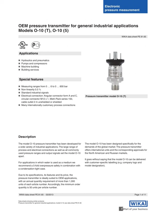
The model O-10 pressure transmitter has been developed for a wide variety of industrial applications. A large range of process and electrical connections, as well as all commonly used pressure ranges and output signals, set the model O-10 apart. For applications in which water is used as a medium, we recommend a 5-fold overpressure safety in combination with a condensation-tight case.<br><br>For More Information visit on our website:- www.instronline.com<br><br>Our E-mail Address:-info@instronline.com <br>

E N D
Electronic pressure measurement OEM pressure transmitter for general industrial applications Models O-10 (T), O-10 (5) WIKA data sheet PE 81.65 Applications ■ Hydraulics and pneumatics ■ Pumps and compressors ■ Machine building ■ Building services Special features ■ Measuring ranges from 0 … 6 to 0 … 600 bar ■ Non-linearity 0.5 % ■ Standard industrial signals ■ Electrical connection: Angular connector form A and C, circular connector M12 x 1, Metri-Pack series 150, cable outlet 2 m unshielded or shielded Pressure transmitter model O-10 (T) ■ Many internationally customary process connections Description The model O-10 has been designed specifically for the demands of the global market. The pressure transmitter offers international units and the corresponding approvals for the North American and Russian markets. The model O-10 pressure transmitter has been developed for a wide variety of industrial applications. The large range of process and electrical connections as well as all commonly used pressure ranges and output signals set the model O-10 apart. It goes without saying that the model O-10 can be delivered with customer-specific labelling (e.g. company logo and model designation). For applications in which water is used as a medium we recommend a 5-fold overpressure safety in combination with a condensation-tight case. Due to its specifications, its features and its price, the pressure transmitter is ideally suited to OEM applications, with an annual quantity requirement of more than 1,000 units of each article number. Accordingly, the minimum order quantity is 50 units per article number. WIKA data sheet PE 81.65 ∙ 03/2013 Page 1 of 11 Data sheets showing similar products: Pressure transmitter for general industrial applications; model A-10; see data sheet PE 81.60
Versions Model O-10 (T) Standard version Model O-10 (5) With 5-fold overpressure limit and condensation-tight case For applications with water as a medium we recommend a 5-fold overpressure safety for protection against water hammer effects, and a condensation-tight case. Measuring ranges ■ Model O-10 (T) Relative pressure bar 0 ... 160 psi 0 ... 600 0 ... 4,000 0 ... 6 1) 2) 0 ... 10 1) 2) 0 ... 250 0 ... 160 0 ... 750 0 ... 5,000 0 ... 16 0 ... 400 0 ... 200 0 ... 800 0 ... 6,000 0 ... 25 0 ... 600 0 ... 250 0 ... 1,000 0 ... 7,500 0 ... 40 0 ... 60 0 ... 100 0 ... 100 1) 2) 0 ... 300 0 ... 1,500 0 ... 8,000 0 ... 400 0 ... 2,000 0 ... 500 0 ... 3,000 Vacuum and +/- measuring range bar psi -1 ... +5 2) -30 inHg ... +100 2) -1 ... +9 2) -30 inHg ... +160 -1 ... +15 -30 inHg ... +200 -1 ... +24 -30 inHg ... +300 -1 ... +39 -30 inHg ... +500 -1 ... +59 1) Measuring deviation of the zero signal ≤ ±0.7 % of span 2) Non-linearity ≤ ±0.6 % of span BFSL The given measuring ranges are also available in kg/cm2, kPa and MPa. Other measuring ranges on request. Overpressure limit 2 times, 3 times on request Vacuum tightness Yes ■ Model O-10 (5) Relative pressure bar 0 ... 6 0 ... 10 0 ... 16 0 ... 25 0 ... 40 Other measuring ranges on request. Overpressure limit 5 times Vacuum tightness Yes Page 2 of 11 WIKA data sheet PE 81.65 ∙ 03/2013
Output signals ■ Model O-10 (T) Signal type Signal Current (2-wire) Voltage (3-wire) 4 ... 20 mA DC 0.5 ... 4.5 V DC 0 ... 5 V DC 1 ... 5 V DC 0 ... 10 V DC 0.5 ... 4.5 V Ratiometric (3-wire) Other output signals available on request. Load in Ω Current output (2-wire): Voltage output (3-wire): Ratiometric output signal (3-wire): ≤ (power supply - 8 V) / 0.02 A > maximum output signal / 1 mA > 4.5 kΩ ■ Model O-10 (T) Signal type Signal Current (2-wire) Voltage (3-wire) 4 ... 20 mA DC 0.5 ... 4.5 V DC 1 ... 5 V DC 0.5 ... 4.5 V Ratiometric (3-wire) Other output signals available on request. Load in Ω Current output (2-wire): Voltage output (3-wire): Ratiometric output signal (3-wire): ≤ (power supply - 8 V) / 0.02 A > maximum output signal / 1 mA > 4.5 kΩ WIKA data sheet PE 81.65 ∙ 03/2013 Page 3 of 11
Voltage supply Power supply The power supply depends on the selected output signal. 4 ... 20 mA: DC 0.5 ... 4.5 V: DC 0 ... 5 V: DC 1 ... 5 V: DC 0 ... 10 V: DC 0.5 ... 4.5 V (ratiometric): DC 8 ... 30 V DC 8 ... 30 V DC 8 ... 30 V DC 8 ... 30 V DC 14 ... 30 V DC 4.5 ... 5 V The power supply for the pressure transmitter must be made via an energy-limited electrical circuit in accordance with section 9.4 of UL/EN/IEC 61010-1, or an LPS to UL/EN/IEC 60950-1, or class 2 in accordance with UL1310/UL1585 (NEC or CEC). The power supply must be suitable for operation above 2,000 m should the pressure transmitter be used at this altitude. Total current consumption Current output: The total current consumption corresponds to the value of the output signal current (4 ... 20 mA), maximum 25 mA Voltage output: 5 mA Reference conditions (per IEC 61298-1) Temperature 15 ... 25 °C Atmospheric pressure 860 ... 1,060 mbar Humidity 45 ... 75 % relative Power supply Current output: Voltage output: Ratiometric output signal: DC 14 V DC 24 V DC 5 V Nominal position Calibrated in vertical mounting position with pressure connection facing downwards. Time response Settling time < 2 ms Page 4 of 11 WIKA data sheet PE 81.65 ∙ 03/2013
Accuracy data ■ Model O-10 (T) Non-linearity (per IEC 61298-2) ≤ ±0.5 % of span BFSL A different non-linearity applies to some measuring ranges, see "Measuring ranges O-10 (T)". Measuring deviation of the zero signal ≤ ±0.5 % of span A different measuring deviation applies to some measuring ranges, see "Measuring ranges model O-10 (T)". Accuracy at reference conditions ≤ ±1.2 % of span Temperature error at 0 ... 80 °C ≤ ±1.5 % of span Long-term stability ≤ ±0.3 % of span/year ■ Model O-10 (5) Non-linearity (per IEC 61298-2) ≤ ±0.5 % of span BFSL Measuring deviation of the zero signal ≤ ±1 % of span Accuracy at reference conditions ≤ ±2.0 % of span Temperature error at 0 ... 80 °C Mean temperature coefficient of zero point: Typical: 0.3 % of span/10 K Maximum: 0.6 % of span/10 K Mean temperature coefficient of span: ≤ ±0.1 % of span/10 K Long-term drift ≤ ±0.8 % of span/year WIKA data sheet PE 81.65 ∙ 03/2013 Page 5 of 11
Operating conditions ■ Model O-10 (T) Ingress protection (per IEC 60529) For ingress protections see "Electrical connections model O-10 (T)" The stated ingress protection only applies when plugged in using mating connectors that have the appropriate ingress protec- tion. Vibration resistance (per IEC 60068-2-6) 20 g (20 ... 2,000 Hz, 120 min.) Shock resistance (per IEC 60068-2-27) 40 g (6 ms), mechanical shock Service life 10 million load cycles Free fall test Resistant to an impact onto concrete from 1 m Permissible temperatures Medium: -30 ... +100 °C Ambient: -30 ... +100 °C Storage: -30 ... +100 °C ■ Model O-10 (5) Ingress protection (per IEC 60529) For ingress protections see "Electrical connections model O-10 (5)" The stated ingress protection only applies when plugged in using mating connectors that have the appropriate ingress protec- tion. Vibration resistance (per IEC 60068-2-6) 20 g (20 ... 2,000 Hz, 120 min) Shock resistance (per IEC 60068-2-27) 40 g (6 ms), mechanical shock Service life 10 million load cycles Free fall test Resistant to an impact onto concrete from 1 m Permissible temperatures Medium: -40 ... +100 °C Ambient: -25 ... +80 °C Storage: -25 ... +80 °C Other temperature ranges on request Page 6 of 11 WIKA data sheet PE 81.65 ∙ 03/2013
Process connections Standard EN 837 Thread size G ⅛ B 2) G ¼ B G ¼ female G ⅜ B G ¼ A 1) 3) 4) M14 x 1.5 3) ⅛ NPT 2) ¼ NPT 1) ¼ NPT female R ¼ 1) R ⅜ PT ¼ 1) PT ⅜ 7/16-20UNF BOSS 1) 3) 9/16-18 UNF BOSS 3) DIN 3852-E ANSI/ASME B1.20.1 ISO 7 KS SAE 1) Optional: Pressure port with a diameter of 6 mm, 0.6 mm, 0.3 mm on request. 2) Maximum measuring range from 0 ... 400 bar. 3) Minimum permissible medium temperature -30 °C, also for model O-10 (5) 4) Maximum overpressure limit 600 bar All process connections are available, as standard, with a pressure port of diameter 3.5 mm. Sealings Process connection per Standard Option DIN 3852-E SAE NBR 1) FPM/FKM 2) FPM/FKM 2) - 1) Minimum permissible medium and ambient temperature -15 °C 2) Minimum permissible medium and ambient temperature -30 °C The sealings listed under "Standard" are included in the delivery. Materials Non-wetted parts ■ Stainless steel 316L ■ PBT GF 30 ■ Cable material (cable outlet) PVC Wetted parts ■ Stainless steel 316L ■ 13-8 PH ■ For sealing materials see "Process connections" Oil and grease free versions are available on request. WIKA data sheet PE 81.65 ∙ 03/2013 Page 7 of 11
Electrical connections ■ Model O-10 (T) Available connections Electrical connection Angular connector DIN 175301-803 A Angular connector DIN 175301-803 C Circular connector M12 x 1 (4-pin) Metri-Pack series 150 1) Cable outlet, unshielded 2) Cable outlet, shielded Ingress protection IP 65 IP 65 IP 67 IP 67 IP 67 IP 67 Wire cross-section - - - - 0.14 mm2 0.14 mm2 Cable diameter - - - - 3.4 mm 4.3 mm Cable lengths - - - - 2 m , 5 m 2 m , 5 m 1) for model O-10 (T) only possible from measuring range 0 ... 60 bar 2) up to a maximum of 80 °C permitted The stated ingress protection (per IEC 60529) only applies when plugged in using mating connectors that have the appropriate ingress protection. Mating connectors are not included in the delivery, but they are available as accessories. Other connections on request. Short-circuit resistance S+ vs. 0V Reverse polarity protection UB vs. 0V Overvoltage protection DC 36 V Insulation voltage DC 750 V ■ Model O-10 (5) Available connections Electrical connection Circular connector M12 x 1 (4-pin) Metri-Pack series 150 Cable outlet, unshielded 1) Ingress protection IP 65 IP 67 IP 67 Wire cross-section - - 0.14 mm2 Cable diameter - - 3.4 mm Cable lengths - - 2 m , 5 m 1) up to a maximum of 80 °C permitted The stated ingress protection (per IEC 60529) only applies when plugged in using mating connectors that have the appropriate ingress protection. Mating connectors are not included in the delivery, but they are available as accessories. Short-circuit resistance S+ vs. 0V Reverse polarity protection UB vs. 0V Overvoltage protection DC 36 V Insulation voltage DC 750 V Page 8 of 11 WIKA data sheet PE 81.65 ∙ 03/2013
Connection diagrams Angular connector DIN 175301-803 A 1) 3) Angular connector DIN 175301-803 C 1) 3) 2-wire 3-wire 2-wire 3-wire UB 1 1 UB 1 1 0V 2 2 0V 2 2 S+ - 3 S+ - 3 Circular connector M12 x 1 1) 2) 3) Metri-Pack series 150 1) 2) 3) 2-wire 3-wire 2-wire 3-wire UB 1 1 UB B B 0V 3 3 0V A A S+ - 4 S+ - C Cable outlet, shielded 1) 3) Cable outlet, unshielded 1) 2) 3) 2-wire 3-wire 2-wire 3-wire UB brown brown UB brown brown 0V blue blue 0V green green S+ - black S+ - white 1) Applies to model O-10 (T) 2) Applies to model O-10 (5) 3) Version with connected shield on request Legend UB 0V S+ Positive power supply terminal Reference potential Positive output terminal Dimensions in mm Complete instrument with angular connector DIN 175301-803 A with angular connector DIN 175301-803 C with M12 x 1 circular connector Weight: approx. 80 g Weight: approx. 80 g Weight: approx. 80 g WIKA data sheet PE 81.65 ∙ 03/2013 Page 9 of 11
Complete instrument with Metri-Pack series 150 with cable outlet Weight: approx. 80 g Weight: approx. 80 g Process connections G G ¼ A DIN 3852-E M14 x 1.5 DIN 3852-E L1 14 14 G G ¼ B EN 837 G ⅜ B EN 837 L1 13 16 G 9/16-18 UNF BOSS 7/16-20 UNF BOSS L1 13 12 G G ¼ L1 17 L2 13 L3 10 D1 Ø 19 G ⅛ NPT ¼ NPT R ¼ R ⅜ PT ¼ PT ⅜ L1 10 13 13 15 13 15 G G ⅛ B EN 837 L1 10 G ¼ NPT L1 17 L2 14 D1 Ø 19 For information on tapped holes and welding sockets, see Technical Information IN 00.14 at www.wika.com. Page 10 of 11 WIKA data sheet PE 81.65 ∙ 03/2013
CE conformity Pressure equipment directive 97/23/EC EMC directive 2004/108/EC, EN 61326 emission (group 1, class B) and immunity (industrial application) RoHS conformity Yes Approvals ■ cULus, safety (e.g. electr. safety, overpressure, ...), USA, Canada ■ GOST-R, import certificate, Russia Approvals see website Accessories and spare parts Mating connector Designation Order number without cable with 2 m cable with 5 m cable Angular connector DIN 175301-803 A Angular connector DIN 175301-803 C Circular connector M12 x 1 (4-pin) ■ with cable gland, metric ■ with cable gland, conduit 11427567 11022485 1439081 11225793 - 11225823 11250186 - 11250194 ■ straight ■ angled 2421262 2421270 11250780 11250798 11250259 11250232 Sealings for mating connectors Designation of the mating connector Order number Angular connector DIN 175301-803 A Angular connector DIN 175301-803 C 1576240 11169479 Only use the accessories and spare parts listed above, otherwise it could lead to the loss of the approval. Ordering information Model / Measuring range / Output signal / Process connection / Electrical connection WIKA data sheet PE 81.65 ∙ 03/2013 Page 11 of 11 03/2013 GB WIKA Alexander Wiegand SE & Co. KG Alexander-Wiegand-Straße 30 63911 Klingenberg/Germany Tel. (+49) 9372/132-0 Fax (+49) 9372/132-406 E-mail info@wika.de www.wika.de