Download
1 / 41
680 likes | 2.57k Vues
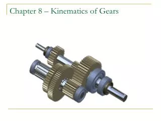
Chapter 8 – Kinematics of Gears. Gears!. Gears are most often used in transmissions to convert an electric motor’s high speed and low torque to a shaft’s requirements for low speed high torque: Speed is easy to generate, because voltage is easy to generate

E N D
Gears! • Gears are most often used in transmissions to convert an electric motor’s high speed and low torque to a shaft’s requirements for low speed high torque: • Speed is easy to generate, because voltage is easy to generate • Torque is difficult to generate because it requires large amounts of current • Gears essentially allow positive engagement between teeth so high forces can be transmitted while still undergoing essentially rolling contact • Gears do not depend on friction and do best when friction is minimized • Basic Law of Gearing: –A common normal (the line of action) to the tooth profiles at their point of contact must, in all positions of the contacting teeth, pass through a fixed point on the line-of-centers called the pitch point –Any two curves or profiles engaging each other and satisfying the law of gearing are conjugate curves, and the relative rotation speed of the gears will be constant
Spur Gears • Teeth are parallel to the axis of the gear • Advantages • Cost • Ease of manufacture • Availability • Disadvantages • Only works with mating gear • Axis of each gear must be parallel
Standard Spur Gears (Berg Master Catalog)
Helical Gears • Teeth are at an angle to the gear axis (usually 10° to 45°) – called helix angle • Advantages • Smooth and quiet due to gradual tooth engagements (spur gears whine at high speed due to impact). Helical gears good up to speeds in excess of 5,000 ft/min • More tooth engagement allows for greater power transmission for given gear size. • Parallel to perpendicular shaft arrangement – Fig 8.2 • Disadvantage • More expensive • Resulting axial thrust component
Helical Gears • Mating gear axis can be parallel or crossed • Can withstand the largest capacity at 30,000 hp
Worm Gears worm gear • Gears that are 90° to each other • Advantages • Quiet / smooth drive • Can transmit torque at right angles • No back driving • Good for positioning systems • Disadvantage • Most inefficient due to excessive friction (sliding) • Needs maintenance • Slower speed applications worm
Bevel Gears • Gear axis at 90°, based on rolling cones • Advantages • Right angle drives • Disadvantages • Get axial loading which complicates bearings and housings
Spiral Bevel Gears • Same advantage over bevel gears as helical gears have over spur gears!! • Teeth at helix angle • Very Strong • Used in rear end applications (see differentials)
Why Use Gears? • Reduce speed • Increase torque • Move power from one point to another • Change direction of power • Split power Generally this functionality is accomplished by many gears mounted in a gear box!
BostonGear Examples of “off the shelf” drives Show slides
Other Drives • Splitter – One input with several outputs • Right Angle – Transfers torque thru right angles, can be as simple as mating bevel gears www.gamweb.com/ power_series.htm Types of Gear Boxes: http://en.wikipedia.org/wiki/Gear_box
Other Drives • Differentials • Engines typically operate over a range of 600 to about 7000 revolutions per minute (though this varies, and is typically less for diesel engines), while the car's wheels rotate between 0 rpm and around 1800 rpm. Engine: higher speed, lower torque versus wheels. www.torsen.com/products/ T-1.htm How a manual transmission works: http://en.wikipedia.org/wiki/Manual_transmission
How a differential works: http://en.wikipedia.org/wiki/Differential_(mechanical_device)
Gears vs Belts and Chains • Gears are much more capable in terms of power rating (helical gear drives capable of > 30,000 hp) • With planetary gear sets large gear ratio’s can be achieved (100:1) • Gear applications include high torque and high speeds • Can have multiple speed reductions by pairing different gears or gear trains (several gears in series)
Gears used for Speed Reducer • Recall the main purpose of mating/meshing gears is to provide speed reduction or torque increase. Gear nG NG Pinion nP NP
Example: Want a 3:1 reduction • NP=22 teeth • What is NG? • Solution: • VR = 3 = NG/NP • NG = 3*22 = 66 teeth Figure 8-15, pg. 322
n4, N4 n1, N1 Engine Pump Given: n1 = 500 rpm, N1 = 20tN2 = 70t, N3 = 18t, N4 = 54t Find: n4 n2, N2 n3, N3 Example: Double Speed Reducer • Solution: • n2 = 500 rpm*(20/70) = 142.8 rpm • n3 = n2 • n4 = 142.8 rpm*(18/54) = 47.6 rpm • Total reduction = 500/47.6 = 10.5 (0r 10.5:1) Torque?? Increases by 10.5!!Power?? Stays the same throughout!
Pinion Line drawn perpendicular at point of contact always crosses centerline at same place then VR = np/nG = constant POWER np Law of Kinematics Holds true if teeth have conjugate profile!! DEMO! Fig 8-7
Spur Gear Nomenclature • Pitch Circle(s) • The circles remain tangent throughout entire engagement • Pitch Diameter • Diameter of pitch circle DP – Pitch f of pinion DG – Pitch f of gear (power gear or driving gear) (Driven gear)
Gear Nomenclature • N = Number of teeth • Use subscript for specific gear • NP=Number of teeth on pinion (driver) • NG=Number of teeth on gear (driven) • NP < NG (for speed reducer) • NA=Number of teeth on gear A • Circular Pitch, P is the radial distance from a point on a tooth at the pitch circle to corresponding point on the next adjacent tooth P=(p*D)/N
Gear Nomenclature • Gear Train Rule – Pitch of two gears in mesh must be identical PINION p DG p DP = P NP NG GEAR
Gear Nomenclature • Diametral Pitch, (Pd) – Number of teeth per inch of pitch diameter *Two gears in mesh must have equal Pd: *Standard diametral pitches can be found in Table 8-1 and 8-2 N = Pd D NG NP = = Pd DP DG
Gear Nomenclature Figure 8-8 More Gear Nomenclature: http://en.wikipedia.org/wiki/List_of_gear_nomenclature
Gear Geometry • Spur Gears • Tooth Profile – Conjugate shape • Conjugate Profile • Tooth is thicker at base, maximum moment • σ = M/s • Pressure Angle (φ) - angle between tangent and perpendicular line to gear tooth surface • Allows constant velocity ratio between mating gears and smooth power transmission Conjugate profile Fillet Radius
Pressure Angle Force perpendicular at f Φ = 14.5˚ Φ = 20˚ Φ = 25˚
Gear Nomenclature Example 8-1) Gear has 44 teeth, Æ=20°, full depth involute form diametral pitch Pd = 12 • Pitch Diameter • Circular Pitch NG 44 teeth 3.667 inch = = = DG 12 t/in Pd p DG (p) 3.667in .2617 in/t = = = Pc NG 44 t
Gear Nomenclature Example • Addendum Dedendum 1 1 a = .0833 in = = Pd 12 t/in 1.25 1.25 b = = .1042 in = Pd 12 t/in
Gear Nomenclature Example • Clearance • Whole Depth ht = a+b = .1875 in • Working Depth hk = 2*a = .16667 in .25 .25 c = = .0208 in = Pd 12 t/in
Gear Nomenclature Example • Tooth Thickness • Outside Diameter PC .2617in t = = .1309 in = 2 2 N+2 O.D. = DO = 2.833 in = Pd
Gear Nomenclature Notes • Clearance maybe a problem for small pinions driving large gears, therefore they won’t mesh and will lock up (See Table 8-6) • As NP decreases so does max NG • If design necessatates small pinion, maybe able to increase clearance by undercutting gear tooth (See Figure 8-14)
Summary of Gear Nomenclature: • DP = Pitch diameter of pinion • DG = Pitch diameter of gear • NP = No. teeth (t) for pinion • NG = No. teeth (t) or gear • Pd = diametral pitch = N/D = constant for meshing gears • p = circular pitch = pD/N = constant for meshing gears • nP = speed of pinion (rpm) • nG = speed of gear (rpm) • VR = velocity ratio = nP/nG = NG/NP • Power = constant across mating gears or series system: • Pin = Pout • Power in branched system is conserved: • Pin = PA + PB + ….. • Torque will change!!
Conclusion: • Total speed reduction = 1750/68 = 25.7 • Torque increase = 25.7 • Power = constant!!
Gear Trains • Train Value = TV = Product of the values for each gear pair in the train nin TV = = (VR1)(VR2). . . . nout
Gear Train Alternate Solution (VR1)(VR2)(VR3) TV = 30 68 68 8.4 = TV = * * 25 22 30 ni TV = nout ni 1750 rpm nout 208 rpm ccw = = = TV 8.4 Tout = 8.4 Tin !! Lots of Torque
YouTube Gear Animations: • Speed Reducers: • http://www.youtube.com/watch?v=7LReoWPg_pM&feature=related • http://www.youtube.com/watch?v=1_jbZVBXjWc&feature=related • Automotive Differential: http://www.youtube.com/watch?v=iBLE0_Sjqw4&feature=related • Manual Transmission: http://www.youtube.com/watch?v=MBmLJCeGu7o&feature=related • Gear Cutting: • http://www.youtube.com/watch?v=fps0OR1eF_s&feature=related • http://www.youtube.com/watch?v=xF9CjluRFJ4&feature=related