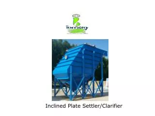
Clarifier
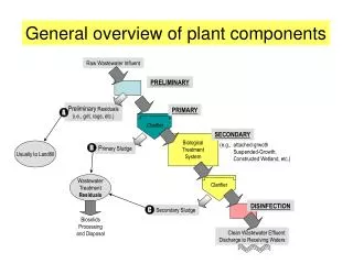
Clarifier. General overview of plant components. Raw Wastewater Influent. PRELIMINARY. Preliminary Residuals (i.e., grit, rags, etc.). PRIMARY. A. Clarifier. SECONDARY. Biological Treatment System. (e.g., attached-grwoth Suspended-Growth,

Clarifier
E N D
Presentation Transcript
Clarifier General overview of plant components Raw Wastewater Influent PRELIMINARY Preliminary Residuals (i.e., grit, rags, etc.) PRIMARY A Clarifier SECONDARY Biological Treatment System (e.g., attached-grwoth Suspended-Growth, Constructed Wetland, etc.) Usually to Landfill Primary Sludge B Wastewater Treatment Residuals Clarifier DISINFECTION Secondary Sludge C Biosolids Processing and Disposal Clean Wastewater Effluent Discharge to Receiving Waters
Biological wastewater (WW) treatment • Toremove the suspended solids & the dissolved organic load from the WW by using microbial populations. • The microorganisms are responsible for • degradation of the organic matter • they can be classified into • aerobic (require oxygen for their metabolism) • anaerobic (grow in absence of oxygen) • facultative (can proliferate either in absence or presence of oxygen).
Biological wastewater (WW) treatment • If the micro-organisms are suspended in the WW during biological operation • suspended growth processes • Recycling of settled biomass is required. • While the micro-organisms that are attached to a surface over which they grow • attached growth processes • The biomass attached to media (ex. rock, plastic, wood) • Recycling of settled biomass is not required.
What can this process do? 1. Remove Nutrient 2. Remove dissolved organic solids Remove suspended organic solids Remove suspended solids Attached Growth Process
Cross-section of an attached growth biomass film Oxygen (the natural or forced draft) Wastewater Organic/ nutrient filter media Biomass : viscous, jelly-like substance containing bacteria
Attached Growth Process • Trickling filter (TF) • Rotating biological contactor (RBC)
Trickling Filter (TF)- side view • TF consists of: • A rotating arm that sprays wastewater over a filter medium. • Filter medium: rocks, plastic, or other material. • The water is collected at the bottom of the filter for further treatment. rotating distributor arms Packing media Underdrain Wastewater
Design consideration • Influent wastewater characteristics • Degree of treatment anticipated (BOD & TSS removal). • Temperature range of applied wastewater • Pretreatment processes • Type of filter media • Recirculation rate • Hydraulic and organic loadings applied to the filter • Underdrainage and ventilation systems
Trickling Filter (TF)- side view • TF consists of: • A rotating arm that sprays wastewater over a filter medium. • Filter medium: rocks, plastic, or other material. • The water is collected at the bottom of the filter for further treatment. rotating distributor arms Packing media Underdrain Wastewater
Design consideration - Pretreatment • Trickling filters shall be preceded by primary clarifiers equipped with scum and grease collecting devices, or other suitable pretreatment facilities. • If fine screening is provided the screen size shall have from 0.03 to 0.06 inch openings. • Bar screens are not suitable as the sole means of primary treatment.
Design consideration • Influent wastewater characteristics • Degree of treatment anticipated (BOD & TSS removal). • Temperature range of applied wastewater • Pretreatment processes • Type of filter media • Recirculation rate • Hydraulic and organic loadings applied to the filter • Underdrainage and ventilation systems
Filter media • Crushed rock • Durable & insoluble • Locally available • But, reduce the void spaces for passage of air • Less surface area per volume for biological growth • Plastic media • Random packing media • Modular packing media
Filter media Cross-flow Tubular Pall rings Schematic diagrams of modular and random packed media used in fixed-film treatment systems (Source: Bordacs and Young, 1998)
Design consideration - Filter media The ideal filter packing is material that • has a high surface area per unit of volume • is low in cost • has a high durability • has a high enough porosity so that clogging is minimized • provides good air circulation
Design consideration • Influent wastewater characteristics • Degree of treatment anticipated (BOD & TSS removal). • Temperature range of applied wastewater • Pretreatment processes • Type of filter media • Recirculation rate • Hydraulic and organic loadings applied to the filter • Underdrainage and ventilation systems
Flow Diagram for Trickling Filters Recirculation= A portion of the TF effluent recycled through the filter Recirculation ratio (R) = returned flow (Qr)/ influent flow (Q) Qr Q
Design consideration - Recirculation • Why is recirculation required? • maintain constant wetting rate • dilute toxic wastes • increase air flow • recirculation flow dilutes the strength of raw wastewater & allows untreated wastewater to be passes through the filter more than once. • A common range for recirculation ratio • 0.5~3.0
Single stage a. PC SC TF PC SC b. TF PC SC c. TF
Two stage PC SC TF TF PC SC SC TF TF PC SC SC TF TF
Design consideration • Influent wastewater characteristics • Degree of treatment anticipated (BOD & TSS removal). • Temperature range of applied wastewater • Pretreatment processes • Type of filter media • Recirculation rate • Hydraulic and organic loadings applied to the filter • Underdrainage and ventilation systems
Underdrain System Two purposes: • (a) to carry the filtered wastewater and the biomass lump (sloughed solids) from the filter to the final clarification process • (b) to provide for ventilation of the filter to maintain aerobic conditions. • The underdrain system is generally designed to flow one-third to one-half full to permit ventilation of the system.
Ventilation systems • In TF system, • Air is supplied by natural draft or forced draft fan. • The forced draft fans have been applied in order to provide the adequate oxygen.
Stone media TF design • Organic (BOD) loading rate: • Expressed as kg/m3/d • Typically, 0.320-0.640 kg/m3/d for single-stage filters • Typically, 0.640-0.960 kg/m3/d for two-stage filters • Ex) Influent BOD =200mg/L, influent flow = 1.8 ML/d, diameter of the filter is 16 m & the depth of the filter is 2m. Calculate the organic loading rate.
Stone media TF design • Hydraulic loading rate: • m3 wastewater/m2 filter*d • the rate of total influent flow is applied to the surface of the filter media • Total influent flow = the raw WW + recirculated flow • Typically, 9.4 m3/m2/d • Maximum, 28 m3/m2/d • Ex) Influent flow = 8.5ML/d, the recirculation ratio is 2:1. Diameter of the filter is 16 m & the depth of the filter is 2m. Calculate the hydraulic loading rate.
Stone media TF design • NRC (national research council) formula where: E1 = BOD removal efficiency for first-stage filter at 20oC, % w1 = BOD load applied, kg/day V = volume of filter media, m3 F = recirculation factor First stage or single stage
Stone media TF design • NRC formula Where: E2 = BOD removal efficiency for second-stage filter at 20oC, % E1 = fraction of BOD removal in the first-stage filter w2 = BOD load applied, kg/day V = volume of filter media, m3 F = recirculation factor Second stage
Stone media TF design • NRC formula where: F = recirculation factor R = recycle ratio
Stone media TF design • The effect of temperature on the BOD removal efficiency where: ET = BOD removal efficiency at ToC, % E20 = BOD removal efficiency at 20oC, %
Stone media TF design • Example 1 • Calculate the BOD loading, hydraulic loading, BOD removal efficiency, and effluent BOD concentration of a single-stage trickling filter based on the following data: • Design assumptions: • Influent flow =1530 m3/d • Recirculation ratio = 0.5 • Primary effluent BOD = 130 mg/L • Diameter of filter = 18 m • Depth of media = 2.1 m • Water temperature =18oC
Stone media TF design • Example 2 • A municipal wastewater having a BOD of 200 mg/L is to be treated by a two-stage trickling filter. The desired effluent quality is 25 mg/L of BOD. If both of the filter depths are to be 1.83 m and the recirculation ratio is 2:1, find the required filter diameters. Assume the following design assumptions apply. • Design assumptions: • Influent flow =7570 m3/d • Recirculation ratio = 2 • Depth of media = 1.83 m • Water temperature =20oC • BOD removal in primary sedimentation = 35% • E1=E2
Stone media TF design • Example 2 BOD=200mg/L BOD=25mg/L Primary Clarifier Secondary Clarifier TF1 TF2
Plastic media Schulze formula • The liquid contact time(t) of applied wastewater Where: t = liquid contact time, min D= depth of media (m) q = hydraulic loading, (m3/m2/h) C, n = constants related to specific surface & configuration of media
Plastic media • hydraulic loading (q) Where: Q= influent flow rate L/min A=filter cross section area m2
Plastic media TF design Schulze formula Where: Se= BOD concentration of settled filter effluent, mg/L So= influent BOD concentration to the filter, mg/L k=wastewater treatability and packing coefficient, (L/s)0.5/m2 D=packing depth, m q= hydraulic application rate of primary effluent, excluding recirculation, L/m2*s n=constant characteristic of packing used (assumed to be 0.5).
Plastic media TF design • Example 3 • Given the following design flow rates and primary effluent wastewater characteristics, determine the following design parameters for a trickling filter design assuming 2 reactors at 6.1 m depth, cross-flow plastic packing with a specific surface area of 90 m2/m3, a packing coefficient n value of 0.5, & a 2-arm distributor system. The required minimum wetting rate=0.5L/m2*s. Assume a secondary clarifier depth of 4.2m and k value is 0.187. • Design conditions
Plastic media TF design • Example 3 • Using the information presented in the previous slide, determine: • Diameter of TF • Volume of packing required. • Recirculation rate required