RANSAC-Assisted Display Model Reconstruction for Projective Display
300 likes | 561 Vues
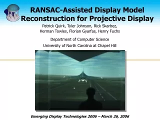
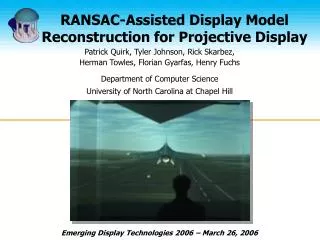
RANSAC-Assisted Display Model Reconstruction for Projective Display. Patrick Quirk, Tyler Johnson, Rick Skarbez, Herman Towles, Florian Gyarfas, Henry Fuchs Department of Computer Science University of North Carolina at Chapel Hill. Emerging Display Technologies 2006 – March 26, 2006.

RANSAC-Assisted Display Model Reconstruction for Projective Display
E N D
Presentation Transcript
RANSAC-Assisted Display Model Reconstruction for Projective Display Patrick Quirk, Tyler Johnson, Rick Skarbez, Herman Towles, Florian Gyarfas, Henry Fuchs Department of Computer Science University of North Carolina at Chapel Hill Emerging Display Technologies 2006 – March 26, 2006
Perspectively-correct Rendering • P matrices • Intrinsics and extrinsics of each projector • Viewer’s location • Display Surface Model New Method for Display Surface Estimation!
Viewer Projector A Primer: 2-Pass Rendering • 1st Pass • Geometry: application defined • Viewpoint: user’s position • Result: “ideal image” • 2nd Pass • Geometry: screen surface • Use “ideal image” as projected texture • Viewpoint: projector’s position • Result: projector’s image Display Surface
Display Surface Estimation Display Surface Model Generation 3D Stereo Reconstruction 3D Point Cloud Tessellated Mesh
Artifacts with Tessellated Meshes • Inaccurate corner representations • Sampling issue • Texture mapping distortion on planar surfaces • Reconstruction errors • Holes in surface model • Meshing errors
Rooms Are Piecewise Planar • New display model estimation method • Fit planes to point cloud • Convert planes to polygons for rendering • Advantage • Corners can be accurately estimated (intersection of planes) • Noiseless models eliminate texture distortion
RANSAC Plane Fitting • Random Sample Consensus • Designed to work with many outliers • Finds largest set of inliers • Code from Peter Kovesi, Univ. Western Australia • Hypothesis plane from 3 random points • Finds plane with most inliers • User specified fit tolerance • Fits least-squares plane to these inliers
Method FitPlane( C ) • Fit one planePto point cloud Cusing RANSAC • Remove P inlier points from cloud C’ = C – Pinliers • Recursively loop using outliers from this pass as input for next plane
Plane To Polygons • Task: What planes intersect? • Reduce complexity to a 2D problem • Establish a “floor” plane orthogonal to the “wall” planes • Project wall points onto this plane • Casts problem as a line intersection problem
Cast into a 2D Task Intersecting Line (Plane) Pairs Red–Orange Orange –Green Green –Cyan Cyan–Magenta Magenta–Black Black–Blue
Results • Less than 2-3% dimensional error • Re-projection: Std. Dev. < 0.5 pixels
Results P V • Improved corner matching (< 2 pixels) • Lack of texture distortion in application scenery
FlightGear Demo P P
Installations • UNC Lab • 3 walls with columns in each corner • UNC lobby and I/ITSEC 2005 • 2-wall corner • Naval Research Lab • 3 walls with a column in one corner
SUMMARY: New Surface Model Generation Method • Recursively extract planes from 3D point cloud with RANSAC-assisted algorithm • Removes outliers easily • Fits noisy data well • Convert Planes to Polygons for 2-pass rendering • Results in simple, accurate model • Much less distortion than with tessellated mesh
Future Work • Use optimal triangulation algorithm • Rather than DLT; less noise in data • Generalized Planes to Polygon solution • Extract other surface functions • Applicability of cylinders, quadrics, etc. • Apply techniques to create larger virtual environments • Continuous calibration/refinement during operation
Thank You • Funding • Office of Naval Research Award N00014-03-1-0589 • DARWARS Training Superiority program • VIRTE – Virtual Technologies and Environments program
Planes to Polygons • Compute intersection line between two planes • Align this with Y axis • Project down all points to get floorplan • Line segments, based on range of inliers • Find closest 2D line intersections • Determines which planes to intersect • Intersect the planes, make height uniform • Truncate non-intersecting planes (edges)
Room Coordinate System • Motivation • Can easily estimate position of viewer • Auto-alignment performed • Incorporated into Planes to Polygons algorithm • Chosen to be intersection of planes • Also have tool to change coordinate system • Extends to a tracked user
3D Stereo Reconstruction • Display feature set with projector(s) • Checkerboard, Gray-coded stripes, Gaussian blobs, etc. • Image with stereo camera pair • Extract, identify, match feature points • Triangulate corresponding points Model represented by 3D point cloud!