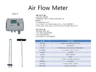
0812-9899-0121 (Bpk. Arief) coriolis flow meter siemens,mass flow meter siemens,flow meter siemens,air flow meter , Jaka
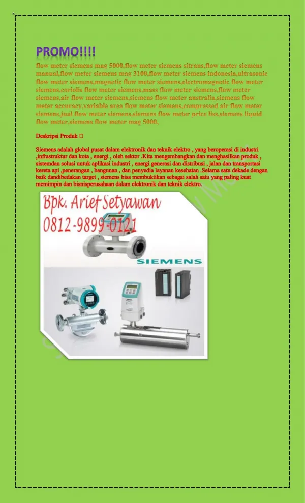
PROMO!!!! flow meter siemens mag 5000,flow meter siemens sitrans,flow meter siemens manual,flow meter siemens mag 3100,flow meter siemens indonesia,ultrasonic flow meter siemens,magnetic flow meter siemens,electromagnetic flow meter siemens,coriolis flow meter siemens,mass flow meter siemens,flow meter siemens,air flow meter siemens,siemens flow meter australia,siemens flow meter accuracy,variable area flow meter siemens,compressed air flow meter siemens,jual flow meter siemens,siemens flow meter price liss,siemens liquid flow meter,siemens flow meter mag 5000, Deskripsi Produk Siemens adalah global pusat dalam elektronik dan teknik elektro , yang beroperasi di industri ,infrastruktur dan kota , energi , oleh sektor .Kita mengembangkan dan menghasilkan produk , sistemdan solusi untuk aplikasi industri , energi generasi dan distribusi , jalan dan transportasi kereta api ,penerangan , bangunan , dan penyedia layanan kesehatan .Selama satu dekade dengan baik dandibedakan target , siemens bisa membuktikan sebagai salah satu yang paling kuat memimpin dan bisnisperusahaan dalam elektronik dan teknik elektro. Hubungi : PT. Vepro Nusa Persada Bpk. Arief Setyawan 0812-9899- 0121 distributorsiemens@gmail.com Website = http://vepronusapersada.com/ http://distributorsiemens.com/ G MAP = http://www.google.com/maps/place/Distributor Siemens Indonesia/@- 6.3038967,106.6840443,17z/data=!3m1!4b1!4m11!1m5!8m4!1e2!2s110295755189674272242!3m1!1e 1!3m4!1s0x2e69e52d33f859e7:0xc6a14631abbf0561!8m2!3d-6.303902!4d106.686233 http://goo.gl/maps/YiXH9WbQX8D2 Linkedin = http://goo.gl/M7az9S http://www.linkedin.com/in/distributorsiemensindonesia FB = http://goo.gl/kuF3eg http://www.facebook.com/DistributorSiemensIndonesia G Plus = http://goo.gl/u4ZvO0 http://plus.google.com/ DistributorSiemensIndonesia Twitter = http://goo.gl/RTkaSj http://twitter.com/agensiemens Jasa Promo Online / Jasa Advertising Online : http://seolangit.com ( 62 812 889 222 45) Support : http://bebrightevent.com/ By : Dwi Haryanto SMK YADIKA VI
103 views • 3 slides