Download
1 / 29
340 likes | 588 Vues
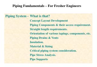
Piping Fundamentals – For Fresher Engineers. Piping System - What is that? Concept Layout Development Piping Components & their access requirement. Straight length requirements. Orientation of various tapings, components, etc. Piping Drains & Vents Insulation.

E N D
Piping Fundamentals – For Fresher Engineers Piping System - What is that? Concept Layout Development Piping Components & their access requirement. Straight length requirements. Orientation of various tapings, components, etc. Piping Drains & Vents Insulation. Material & Sizing Critical piping system consideration. Pipe Stress Analysis. Pipe Supports
Piping Fundamentals – For Fresher Engineers Let us first Discuss about WHAT IS PIPE! It is a Tubular item made of metal, plastic, glass etc. meant for conveying Liquid, Gas or any thing that flows. It is a very important component for any industrial plant. And it’s engineering plays a major part in overall engineering of a Plant. In next few pages we shall try to familiarize about pipe and it’s components.
In any plant various fluids flow through pipes from one end to other. Now let us start with a plant where we see three tanks. Tank-1, Tank-2 and Tank-3 We have to transfer the content of Tank no. 1 to the other two tanks. We will need to connect pipes to transfer the fluids from Tank-1 to Tank-2 and Tank-3 LET US BRING THE PIPES.
Even some pipes are of different sizes! We need some branch connections We need some bend connections We have just brought the pipes, now we need to solve some more problems. Pipes are all straight pieces. To solve these problems we need the pipe components, which are called PIPE FITTINGS
Anyway, the pipes and fittings are in place, but the ends are yet to be joined with the Tank nozzles. These are the pipe fittings, There are various types of fittings for various purposes, some common types are - Elbows/Bends, Tees/Branches, Reducers/Expanders, Couplings, Olets, etc. We now have to complete the end connections. These, in piping term, we call TERMINAL CONNECTIONS.
These are flanged joints This is a welded joint So far this is a nice arrangement. But there is no control over the flow from Tank-1 to other tanks. We need some arrangement to stop the flow if needed To control the flow in a pipe line we need to fit a special component. That is called - VALVE
There are many types of valves, categorized based on their construction and functionality, Those are - Gate, Globe, Check, Butterfly, etc. Other than valves another important line component of pipe line is a filter, which cleans out derbies from the flowing fluid. This is called a STRAINER
If this tank nozzle expands, when the tank is hot. Here we see a more or less functional piping system, with valves and strainer installed. Let us now investigate some aspects of pipe flexibility. In such case we need to fit a flexible pipe component at that location, which is called an EXPANSION JOINT
When some fluid is flowing in a pipe we may also like know the parameters like, pressure, temperature, flow rate etc. of the fluid. To know these information we need to install INSTRUMENTS in the pipeline.
There are various types instruments to measure various parameters. Also there are specific criteria for installation of various pipe line instruments. Next we shall look into how to SUPPORT the pipe/and it’s components.
Here are some of the pipe supporting arrangements. There can be numerous variants. All depend on piping designer’s preference and judgement. Let us see some OTHER types of supports
We have just completed a pipe line design. • We shall rewind and check how it is really done in practice. • First the flow scheme is planned, 1) What, 2) From what point, 3) To which point • Pipe sizes are selected, pipe material and pipe wall thickness are selected. • Types of Valves are planned • Also the types of instruments required are planned • We represent the whole thing in a drawing which is called Piping and Instrumentation Drawing, in short P&ID. For P&ID generation we use SPP&ID software. • By this time you have already come to know that while we prepare P&IDs in SPP&ID, we enter all the pipe lines system information in the drawing. • So the SPP&ID drawing is an Intelligent drawing which under it’s surface carries all the information about a pipe like, Pipe size, Flowing Fluid, etc. • Let us see a P&ID prepared in SPP&ID
This is screen picture of P&ID made by SPP&ID If we click on any line it will show the Data embedded.
Not Preferable Preferable After the P&ID is ready we start the layout work. Here we carryout pipe routing / layout in Virtual 3D environment. We use PDS 3D software to route piping in the Plant virtual 3D space. We call this as piping modeling or physical design. • While development of piping layout we have to consider the following • Piping from source to destination should be as short as possible with minimum change in direction. • Should not hinder any normal passage way. Also should not encroach any equipment maintenance space.
Example of Straight length requirement for Flow Orifice • While carrying out pipe routing we also need to consider the following • Valves, strainers, instruments on the pipe should be easily accessible. • If needed separate ACCESS PLATFORMS to be provided to facilitate these. • Desired location and orientation of valves / instruments and other pipe components are to be checked and maintained, like some valves or strainers can only be installed in horizontal position. • Specific requirements for instrument installation to be checked, like temperature gauge can not be installed in pipe which is less than 4 inch in size. • Specific requirements of STRAIGHT LENGTH of pipe for some components to be maintained, like for flow orifice we need to provide 15 times diameter straight pipe length at upstream of orifice and 5 times diameter straight at down stream of orifice.
PIPELINE DRAINS AND VENTS • For Pipeline which shall carry liquid, we have to make sure that all air is allowed to vent out of the line when the line is filled with liquid. • To achieve this a VENT connection with Valve is provided at the top most point of the pipeline. • Also arrangement is kept in the pipeline so that liquid can be drained out if required. • To achieve this a DRAIN connection with Valve is provided at the lowest point of the pipeline • Pipes are also slopped towards low points. Let us look into typical Vent and Drain arrangement in a pipeline
This is a 3D model of Feed water line along with pumps and other accessories Let us have a look into a piping model done by PDS 3D
INSULATION- When hot fluid flows through pipe then generally pipe is insulated. • There are two primary reasons for insulating the pipe carrying hot fluid. • Containing the heat inside the pipe. Insulation preserves the heat of the fluid. It is called Hot Insulation • Personnel safety, so that people do not get burn injury by touching hot surface of pipe. It is called Personnel Protection Insulation INSULATION Cold pipes are also insulated • Cold or chilled fluid carrying pipes are insulated to prevent heating of cold fluid from outside. It is called Cold Insulation. • Some times cold pipes are insulated to prevent condensation of atmospheric water vapor on pipe surface. It is called Anti-Sweat Insulation. Other types of Insulation • When gas flows through pipes at high velocity, it creates noise. In such cases pipes are insulated to reduce noise. It is called Acoustic Insulation. • Some times pipe and it’s content are heated from outside, by heat tracing element. In that case pipe along with heat tracing element are insulated to conserve the heat of the tracer. It is called Heat Tracing Insulation.
INSULATION MATERIAL - The insulating material should be bad conductor of heat. There are two basic categories 1) Fibrous Material, which has large voids full of air between fibers - Cork, Glass Wool, Mineral Wool, Organic Fibers. Note stagnant air is a bad conductor. 2) Cellular Material, which has closed void cells full or air - Calcium Silicate, Cellular Glass (Foam Glass), Polyurethane Foam (PUF), Polystyrene (Thermocol), etc. Some times Cast material like Cement Plaster or Plaster of Paris are also used. INSULATION CLADDING - Insulation materials are generally soft or fragile. So the outer surface of insulation are protected with Aluminum sheet or GI sheet cladding. Have a look at how pipes are insulated, and general components of insulation
Pipe Material Selection - to select appropriate pipe material based on flowing fluid property. Find out type of Fluid flowing Find out Fluid Temp. & Pressure Check Pipe life Expectancy Select suitable Material per practice (Note-1) Check Mat. Listed in Design Code Pipe Material OK YES NO Note-1 : Material is selected per past experience with cost in mind and per material listed in design code. If material is not listed in code we may select next suitable material listed. See Note-1 Pipe Sizing Calculation - to select required pipe diameter based on velocity and pressure drop. Find out Flow volume per second Check Velocity Allowable per second Calc. flow area required and Pipe size Calc. Press. Drop for that Pipe size Check Press. Drop meets Press. Budget Pipe Size OK YES Pipe Thickness Selection - to select appropriate pipe thickness based on flowing fluid property. NO Select Mat. & Diameter as above Find out Fluid Temp. & Pressure Decide on Corrosion allowance Calc. Pipe Thickness per Code Increase Pipe Size Piping Calculations
In Power plant there are some piping which carries steam at high pressure and temperature. And also there are piping which carries water at High pressure. These pipes carries the main cycle steam and water of the steam power plant. • These pipelines are call the CRITICAL PIPING. • Very special care are taken for design of these piping. • First the pipe material selection for such piping is very important as it has to withstand the high pressure and may be also high temperature. • As these pipes carry the main system fluid of the power plant, they are given the right of way, and routed at beginning of the overall plant layout. CRITICAL PIPING • Steam pipes run at very high temperature and the hot pipes expand. We have to built in flexibility in the high temperature pipe routing so that the expansion force is absorbed within the piping. • Also there should be enough flexibility in these pipe routing so that high loads are not transferred to the nozzles of Turbine or Pumps • There are many recognized international codes which lay down guide lines and mandatory requirements for design of such piping. • The most important codes used by power plant piping engineers are • ASME ANSI B31.1- Power Piping Code & IBR - the Indian Boiler Regulation
Pipe Stress Analysis • We have already seen that some of the pipes are subjected to high pressure and high temperature. Also pipes carry the load of the flowing fluid. • We need to check and confirm the pipe is not going to fail with these loading. • This process of checking the stress developed in the piping due to various loading is called Pipe Stress Analysis/Flexibility analysis. • In the process of Analysis we apply various postulated loading on the pipe and find out the stress resulted from these loading. • Then we check with governing codes if those stresses generated are acceptable or not. PIPE STRESS ANALYSIS • We check support load & movement for various loading condition. • We also check out the terminal point loading generated from pipe to the equipment connected to the pipe. This loading are to be within acceptable limits of the equipment suggested by the vendors. • We also find out the pipe growth due to change in temperature and need to keep the movement of pipe within acceptable limits. • Pipe Stress Analysis is an Interactive and Iterative process. Each step is checked • If a check fails we have to go back, modify the layout and restart the analysis.
PIPE STRESS ANALYSIS Inputs • Geometric layout of Pipe • Pipe supporting configuration • Pipe Diameter and Thickness • Pressure inside Pipe • Cold and Hot temperatures of Pipe • Weight of Pipe and insulation • Weight of carrying Fluid • Pipe material Property (Young’s Modulus, Thermal Expansion Coefficient) • Thrust on pipe due to blowing wind. • Thrust on pipe due to earthquake • Load of Snow on pipe • Any transient loading like Steam Hammer load • Any other load on the piping Tools we use • PIPSYS - is an integrated pipe stress analysis module of PLADES 2000 • CEASER - Commercial Piping analysis software • There are many other commercial software available Outputs • Stress of the pipe at various loading conditions • Load at various supports and restrains. • Movement of pipe at support locations • Pipe terminal point loading. Codes and Standards • In general Power Plant Piping have to comply stipulations of ASME ANSI B31.1 • In India Power cycle Piping to comply IBR code requirements.
Constant Load Spring Variable Spring Rigid Hanger Rigid Support Dynamic Support, Snubber Rigid Support Types of Pipe Supports In the beginning of this discussion we talked about various types of pipe supports. Here is some elaboration • There are three general types • Rigid type (no flexibility in the direction of restrain) • Spring type (Allows pipe movement in direction of loading) • Dynamic Support (Degree of restrain depends on acceleration of load) • There are two types of spring support • Variable load type, here support load changes as the pipe moves. • Constant load support, the load remains constant within some range of movement.
Some Special Considerations for Piping When pipes are routed UNDER GROUND (Buried) following points to be kept in mind: • Minimum pipe size to be routed under ground shall be not less than1 inch. • Avoid flange joint in U/G piping. • Keep in mind if pipe leaks U/G, it will be difficult to detect, so avoid U/G routing of pipe carrying hazardous fluid. • Pipe to be laid below Frost Zone at areas where ambient temperature goes below freezing. • U/G, Buried piping should be properly protected from corrosion. • Pipe may be properly wrapped and coated to prevent corrosion. • Or U/G piping be protected by using Cathodic protection. Freeze Protection of outdoor Piping: • In the areas where the ambient temperature goes below freezing there is a possibility that the liquid content of pipe may freeze while the plant is under shut down. • For similar case pipes are wrapped with heat tracing elements to maintain the content temperature above freezing (around 4 deg. C) even when the ambient temp. is below freezing. • Electric Heat tracing is done by wrapping electric coil around pipe, which turns on as the ambient temperature goes down. Pipes are insulated over the heat tracing coils. • Heat tracing can also be done by winding Steam tubes around main pipes.
We have come to the End of Session. Hope you have gathered the fundamentals on the subject of Piping