STARTING SYSTEM
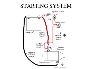
STARTING SYSTEM. STARTING SYSTEM. STARTING SYSTEM. Battery provides the current to turn the starter motor. Fuse protects the circuit. Ignition switch closes the circuit. Relay uses small amount of current to control large amount. .

STARTING SYSTEM
E N D
Presentation Transcript
STARTING SYSTEM Battery provides the current to turn the starter motor. Fuse protects the circuit. Ignition switch closes the circuit. Relay uses small amount of current to control large amount. Neutral safety switch opens the circuit until the vehicle is in neutral (manual transmission), or park (Automatic). (Can be adjusted) Solenoid does the same thing as relay, but performs mechanical operation. It is an electromagnetic switch. Starter motor engages pinion gear to ring gear (mounted on flywheel, Or torque converter).
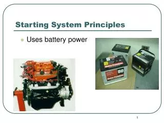
STARTING SYSTEM • Starting system uses battery power and an electric DC motor to turn • engine crankshaft for engine starting. • Changes electrical energy to mechanical. • Provides gear reduction/torque multiplication (16:1 to 20:1). • When the ignition key is turned on the current flows through the • solenoid coil. This closes the contacts, connecting battery to the • starter motor.
STARTING SYSTEM Inside the starter motor. • Starter solenoid • Starter drive/bendix • Starter armature • Starter brushes • Starter bearings
STARTING SYSTEM COMMUTATOR sliding electrical connection between the motor windings and the brushes. • Insulated from each other. • Several loops of wire and a • commutator with many segments • are used to increase motor power • and smoothness.
STARTING SYSTEM BRUSHES ride on top of the commutator to carry battery current to spinning windings. • Replaced during starter rebuilding.
STARTING SYSTEM Starter Armature consists of the armature shaft, armature core, commutator and armature windings. • Armature must produce high torque and high speeds.
STARTING SYSTEM Field winding is a stationary insulated wire wrapped in a circular shape. It creates a strong magnetic field around the motor armature.
STARTING SYSTEM Pinion Gear is attached to the starter drive and when starting the vehicle the pinion gear engages with flywheel or ring gear. It is moved by the YOKE.
STARTING SYSTEM Overrunning Clutch Starter • Locks it in one direction and unlocks it in another. • It allows the pinion gear to run free when engine begins to run.
STARTING SYSTEM Gear Reduction Starter • Has an extra gear on the armature to further increase the rotating force • Gear ratio between flywheel and armature is 45:1 • Hence, the armature turns 45 times to turn the flywheel (engine) once. • This provides high cranking torque for starting.
STARTING SYSTEM DC electric motors have three common types of internal connections: Series-wound motors develop maximum torque at initial start-up. Torque decreases as motor speed increases. Shunt-wound motors have less starting torque but more constant torque at varying speeds. Compound-wound motors have both series and shunt windings. They have good starting power with fairly consistent operating speeds.
STARTING SYSTEM Starting Solenoid • Is a high current relay (controlled by • low current) • Works as an electromagnet switch • If faulty it will simply make a • clicking sound when one is attempting • to start the vehicle.
STARTING SYSTEM Neutral safety switchprevents the vehicle from starting while in gear. (can be adjusted) Clutch Safety Switch prevents the vehicle from starting, unless the clutch pedal is pressed. (adjustable)
STARTING SYSTEM When replacing a starter motor, make sure the spacer shims are of correct thickness are installed. • Shims sit in between the starter • housing and the engine block. If these shims are left out, the pinion gear may not mesh with the flywheel gear properly, and might cause damage to the ring-gear. • Starter metallic grinding • sound.
STARTING SYSTEMQUICK TESTING No crank with no headlights • Dead Battery(corroded terminals) • or an open in electrical circuit. • Burned fuse. • Burned or broken wire.
STARTING SYSTEMQUICK TESTING Head lights go out when cranking • Indicates heavy current draw. • Battery may be weak. • Starter motor may be shorted.
STARTING SYSTEMQUICK TESTING Lights stay bright but, no crank • High resistance or an open in starting circuit. • Possibly Ignition switch • Wiring , solenoid, cable connections, relay, fuse.
STARTING SYSTEM Current Draw Testmost of the starters draw over 200 Amps. • Hookup the VAT • Disconnect Fuel/ignition • Crank engine for 5-10 seconds and note the voltage. • Load the battery until same voltage is obtained • and record the Amp. • The Amps will equal the current drawn by • the starting motor. 4 Cylinder – 150/200 amps 6 Cylinder – 175/250 amps 8 Cylinder – 225/300 amps
STARTING SYSTEM Voltage Drop Test checks for high resistance across a cable/connection • Disable ignition/fuel • Hook voltmeter between +ve battery post and +ve starter terminal • Hook voltmeter between -ve battery post and starter ground. • Crank the engine (5-10Sec.), Voltmeter should not read more • then 1volts. • If greater: • Loose electrical connections. • Burned or pitted solenoid contacts.