1998 cessna 172 s
This presentation is based on the POH for the 1998 Cessna 172 S, and covers the following sections of that manual. . Section 3 Emergency Procedures. Section 2 Limitations. Section 1 General. Section 4 Normal Procedures.


1998 cessna 172 s
E N D
Presentation Transcript
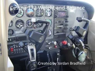
1. 1998 Cessna 172 S For Training Use Only
Obtain actual weights, c.g, fluid capacities and dimensions from the Pilot Operating Handbook for your actual Training airplane.
2. This presentation is based on the POH for the 1998 Cessna 172 S, and covers the following sections of that manual. Section 1 General
3. Remember to verify all information with your actual POH
4. Section 1 Descriptive Data
5. Aircraft Dimensions
6. Aircraft Dimensions
7. Engine
8. Engine Manufactured by Textron Lycoming
9. Propeller
10. Propeller Manufactured by McCauley
11. Fuel
12. Fuel
13. Fuel 2 integral tanks [one in each wing] hold the fuel
The Un-usable fuel includes fuel in the feed lines within the wing struts, Fuel Reservoir, and associated plumbing
The System is Gravity Feed, and uses an Electric Auxiliary Fuel Pump for priming the Fuel Injection system
There are 13 Fuel Drains
5 below each wing tank
3 below the nose
These drains should be tested for water and contamination prior to flight
14. Fuel This aircraft is equipped with a Fuel Selector Valve that allows Fuel to flow from Left, Right, or Both Fuel tanks. BOTH is the Normal selection.
A FUEL SHUT-OFF is also installed in this aircraft for use in Emergency Procedures, or for prolonged Storage.
15. Fuel Total Capacity 56 gallons
Total Useable 53 gallons
Total Each Tank 28 gallons
Total Useable 26.5 gallons
Non-Useable 3 gallons
16. OIL Grade appropriate to temperature ranges
Often this is 15w50 or 20w50
Check Maintenance Records for actual type used in your aircraft.
17. Electrical System System is 28 Volt DC
Powered by a belt driven 60 amp alternator
Supplying a 24 Volt Battery
Battery is located forward of Firewall, Left Side
Current is supplied Through Split Primary Bus Bars 1 and 2
Essential Bus is wired between the 2 primaries to energize Master,
�..Annunciator, and Interior Lighting
Each Primary is connected to an Avionics Bus by the Avionics Master
Continued�����.
18. Electrical SystemContinued Master Switch is a Split Rocker type switch labeled MASTER
On is in the up Position, Off is in the Down Position
The Right Half is labeled BAT and connects Battery Power to Buses
The Left Half is labeled ALT, connects the Alternator
Normally, BAT and ALT are used simultaneously
BAT can be turned on to check electrical equipment on the ground
When the ALT switch is OFF the entire system runs on battery
19. Electrical SystemContinued LOW VOLTAGE Annunciator, Will Illuminate when Voltage falls below 24.5 Volts
OVERVOLTAGE :Alternator Control Unit automatically opens the ALT FLD circuit breaker, Shutting Off the Alternator
Under these conditions, with normal power use, a low voltage condition will occur eventually, and the Low Volt annunciator will illuminate
The Alternator Control unit may be then reset by resetting the ALT FLD circuit breaker
If this occurs a second time, terminate the flight
20. Maximum Certificated Weights Ramp Weight Normal Category 2558
Ramp Weight Utility Category 2208
Takeoff Weight Normal Category 2250
Takeoff Weight Utility Category 2200
Landing Weight Normal Category 2550
Landing Weight Utility Category 2200
21. Baggage Compartment Weights Normal Category
Area 1 120 lbs
Area 2 50 lbs
Maximum Combined Area 1 and 2 120 lbs
22. Baggage Compartment Weights Utility Category
In this Category the Rear Seat must be un-occupied, and the baggage compartment must be empty.
23. Standard Airplane Weights Standard Empty Weight 1663
Normal Category Useful load 895
Utility Category Useful Load 545
24. Specific Loadings Wing Loading: 14.7 lbs./sq. ft.
Power Loading: 14.2 lbs./sq. ft.
25. Baggage Compartment Weights Relate to Category Normal Category
Area 1 120 lbs
Area 2 50 lbs
Maximum Combined Area 1 and 2 120 lbs
26. Section 2 Limitations
27. Airspeed Limitations
28. Airspeed Limitations VNE [ Red Line ]
29. Airspeed Limitations VNO [Upper Limit of Green Arc ]
30. Airspeed Limitations VA
31. Airspeed Limitations Flap Extension
32. Airspeed Limitations VFE
33. Airspeed Limitations Max window open speed
34. Airspeed Indicator Markings White Arc 40 - 85
35. Airspeed Indicator Markings Green Arc 48 - 129
36. Airspeed Indicator Markings Yellow Arc 129 - 163
37. Airspeed Indicator Markings Red Line 163
38. Power Plant Limitations Maximum Power
39. Power Plant Limitations Engine Operating Limits for Takeoff and Continuous Operations
40. Power Plant Limitations Static RPM Range at Full Throttle
41. Power Plant Limitations Maximum Oil Temperature
42. Power Plant Limitations Oil Pressure
43. Power Plant Limitations Oil Grade
44. Power Plant Limitations Engine Oil :
15w50 or 20w50
Check Maintenance Records for actual type used in your aircraft.
45. Power Plant Instrument Markings Tachometer
46. Power Plant Instrument Markings Oil Temperature
47. Power Plant Instrument Markings Oil Pressure
48. Power Plant Instrument Markings Fuel Quantity
49. Power Plant Instrument Markings Fuel Flow
50. Power Plant Instrument Markings Vacuum Gage
51. Normal and Utility Categories Review of Category of Aircraft
52. Normal and Utility Categories FAR Part 23 Normal Category
53. Normal and Utility Categories FAR Part 23 Normal Category
54. Normal and Utility Categories FAR Part 23 Utility Category
55. CG Limits and Categories FAR Part 23 Utility Category
56. Normal Category Weight Limits Ramp Weight 2558
Takeoff Weight 2550
Landing Weight 2550
Baggage Area 1 120
Baggage Area 2 50
Combined Baggage 120
57. Normal Category CG Limits Forward Limit:
35 inches aft of datum at 1950 lbs or less
To 41 inches aft of datum at 2550 lbs.
58. Utility Category Weight Limits Ramp Weight 2208
Takeoff 2200
Landing 2200
Baggage Area 1 and 2 Empty
Rear Seat Empty
59. Utility Category CG Limits Forward Limit:
35 inches aft of datum at 1950 lbs or less
To 37.5 inches aft of datum at 2200 lbs.
60. Maneuver LimitsNormal Category Any maneuver incidental to normal flying
Stalls Slow Deceleration
Steep Turns 95 knots
Chandelles 105 knots
Lazy Eights 105 knots
Spins are not mentioned in the POH under Normal Category limits, and are considered prohibited in this category.
61. Maneuver LimitsUtility Category Any maneuver incidental to normal flying
Stalls Slow Deceleration
Steep Turns 95 knots
Chandelles 105 knots
Lazy Eights 105 knots
Spins Slow Deceleration
62. Flight Load Factor LimitsNormal Category
63. Flight Load Factor LimitsUtility Category
64. Kinds of Operation Limits
65. Fuel Limitations
66. Fuel Limitations
67. Fuel limitations To maximize fuel loading, place the fuel selector to Left or Right.
This prevents Cross-Feed during fueling
There are safety consideration with operating on just one tank.
68. Fuel Limitations
69. Fuel Limitations
70. Fuel Limitations
71. Fuel Limitations
72. Other Limitations
73. Section 3 Emergency Procedures
74. Airspeeds for Emergency Operation
75. Airspeeds for Emergency Operation
76. Airspeeds for Emergency Operation
77. Airspeeds for Emergency Operation
78. Emergency ProceduresChecklists
79. Engine Failure During Takeoff Throttle Idle
Brakes Apply
Flaps Retract
Mixture Idle Cut-off
Ignition Off
Master Off
80. Engine Failure Immediately After Takeoff Airspeed 70 flaps up 65 flaps down
Mixture Idle Cut-off
Fuel Shutoff Off PULL OUT
Ignition Off
Flaps As Required
Master Off
Doors Open
Land Straight Ahead Best Site
81. Engine Failure During Flight[Restart Procedure] Airspeed 68
Fuel Shutoff ON PUSH ON
Fuel Selector Both
Auxiliary Fuel Pump On
Mixture Rich [if Restart has not occurred]
If Prop is windmilling, the engine will restart within a few seconds.
If Prop has stopped turning, Turn Ignition to START
Advance Throttle Slowly from Idle, the adjust mixture for smoothness
If The FUEL FLOW drops to Zero, Turn on Auxiliary Fuel Pump
82. Precautionary Landing Without Engine Power Passenger Seat Backs Upright Position
Seats and Seat Belts Secure
Airspeed 70 Flaps Up 65 Flaps Down
Mixture Idle Cut Off
Fuel Shutoff Valve OFF PULL OUT
Ignition Off
Flaps As Required [30 deg. advised]
Master Off
Doors Open
Touchdown Slightly Tail Low
Brakes Apply Heavily
83. Precautionary Landing With Engine Power Passenger Seat Backs Upright Position
Seats and Seat Belts Secure
Airspeed 65
Flaps 20 degrees
Selected Field : Fly over to evaluate, Climb to appropriate patter altitude and retract Flaps at safe airspeed
Avionics Master Off
Flaps 30 degrees on Final
Airspeed 65
Master Off
Doors Open
Touchdown Slightly Tail Low
Ignition Off
Brakes Apply Heavily
84. Ditching Review POH for this Procedure
Minimize Descent to 300 FPM at 55 kts
Prepare to protect Face with available items
Open Doors
Activate ELT
Touchdown parallel to swells, Level Attitude
Evacuate Airplane
Use Floatation Devices OUT OF AIRPLANE
85. FIRE During Engine Start[Engine has started] Ignition Start, continue cranking for a start
Set Power to 1800 RPM
Follow Shutdown Procedures
Evacuate and Inspect for Damage
86. Engine Fire During Start[Engine has not started] Throttle Full Open
Mixture Idle Cut-off
Cranking Continue
Fuel Shut-Off OFF PULL OUT
Auxiliary Fuel Pump Off
Fire Extinguisher Activate
Engine Secure
Master Off
Ignition Off
Brake Set
Passengers and Crew Evacuate
Fire Extinguish as Required
Inspect for Damage
87. Engine Failure In Flight Mixture Idle Cut Off
Fuel Shutoff Valve Off Pull OUT
Auxiliary Fuel Pump Off
Master Off
Cabin heat and air Off except overhead vents
Airspeed 100 Knots or more to create a non combustible fuel air mixture
Forced Landing Refer to Forced Landing Checklist
88. Electrical Fire in Flight Master OFF
Avionics OFF
All Electric OFF [except magnetos]
Vents/Cabin Air/Heat Closed
Fire Extinguisher Activate [if available]
If Extinguisher is activated, open all vents after fire is out to clear cabin
If fire appears to be out, and electrical power is necessary,
Master ON
Circuit Breakers Check for faulty circuit
Avionics ON, 1 system at a time with a delay in order to evaluate and detect the bad circuit
89. Blocked Static Source[ERRONEOUS INSTRUTMENT READING SUSPECTED] ALTERNATE STATIC PORT OPEN
AIRSPEED CONSULT CALIBRATION TABLE
90. Landing with a Flat Main Tire APPROACH NORMAL
TOUCHDOWN
GOOD TIRE FIRST, HOLD AIRPLANE OFF FLAT TIRE AS LONG AS POSSIBLE.
91. Electrical Power Malfunctions Ammeter shows excessive rate of charge
Alternator OFF
Alternator Breaker PULL
Non-essential equipment OFF
Flight Terminate ASAP
92. Vacuum System Failure Left Vacuum [L VAC] or Right Vacuum [L VAC] Annunciator Illuminates
If Vacuum is not within normal limits, a failure has occurred.
Partial Panel Procedures will be necessary for continued flight
93. Landing without Elevator Control Trim for level flight
Set speed for approximately 65
Once trimmed, do not move elevator trim.
Control glide with power only.
At flare-out, Power reduction will cause nose to drop� Adjust Trim Full UP during power reduction.
94. SPIN RECOVERY THROTTLE IDLE
AILERONS NEUTRAL
RUDDER FULL OPPOSITE OF ROTATION
CONTROL YOKE FORWARD TO BREAK STALL
HOLD THESE CONTROL POSITIONS UNTIL ROTATION STOPS
AS ROTATION STOPS, NEUTRALIZE RUDDER
RECOVER FROM DIVE SMOOTHLY.
95. Section 4 Normal Procedures
96. Before Start Preflight Inspection Complete
Passenger Briefing Complete
Seats and Belts Adjust
Brakes Test and Set
Electrical Equipment Off
Avionics Off
Fuel Selector Both
Fuel Shutoff Valve On PUSH IN
Circuit Breakers Check In
97. Starting Engine [with battery] Throttle Open � inch
Mixture Idle Cut-Ott
Propeller Area Clear
Master On
Flashing beacon On
Auxiliary Fuel Pump On
Mixture Full Rich until a positive fuel flow, then Idle Cut-Off
Auxiliary Fuel Pump Off
Ignition Start
Mixture Advance as Engine Starts
Oil Pressure Check
Navigation Lights As Required
Avionics On
Flaps Retract
98. Starting Engine [Flooded Sart] If Engine floods [over primed] perform the following and then complete the normal start checklist
Auxiliary Fuel Pump OFF
Mixture Idle Cut-Off
Throttle Open � to Full Throttle
Ignition Start
When Engine starts Mixture to Full Rich, Throttle to Idle Promptly.
99. Before Taxi This is not a Cessna Checklist, but will be useful in developing good habits at towered airports.
ATIS Information Obtain and copy with I.D.
Clearance Obtain and copy, READBACK
TRANSPONDER SET Code and Select STBY
Taxi Instructions Comply as Instructed
100. Before Takeoff Parking Brake Set
Seats Upright
Seat Belts Secure
Doors Closed and Latched
Flight Controls Free and Correct
Flight Instruments Check and Set
Fuel Quantity Check
Mixture Full Rich
Fuel Selector Valve Recheck Set to BOTH
Throttle 1800
Magnetos Check drop <150, Diff. Max of 50
Vacuum Gage Check
Annunciator Panel Check
Throttle Check IDLE
Throttle Set to 1000 RPM �..Continued�.
101. Before Takeoff�continued Throttle Friction Lock Adjust
Radios and Avionics SET
NAV/GPS Switch SET
Autopilot OFF
Manual Trim Set for Takeoff
Flaps Set for Takeoff
TRANSPONDER ON
Brakes Release
TAKEOFF CLEARANCE Obtain
TRANSPONDER ON Select ALT
Directional Gyro Set when aligned with Runway
Strobes and Landing Light On when taking Active Runway
102. Normal Takeoff Flaps 0 � 10 Degrees
Throttle Full Open
Mixture Rich (above 3000 ft, Lean for max rpm)
Elevator Lift Nose Wheel at 55
Climb Speed 70-80 [80 Provides better Forward Visibility]
Flaps Retract
103. Short Field Takeoff Flaps 10 Degrees
Brakes Apply
Throttle Full Open
Mixture Rich (above 3000 ft, Lean for max rpm)
Brakes Release
Elevator Slightly Tail Low
Climb Speed 56 Until Obstacles Cleared
Flaps Retract Slowly after reaching 60 knots
104. Enroute Climb Airspeed 70-85
Throttle Full Open
Mixture Rich (lean above 3000 ft)
105. Cruise Power Set 2100-2700 no more than 75%
Elevator Trim Adjust
Mixture Lean For Performance Desired
Arrival Checklist Prepare
106. Arrival(not a Cessna List) Arrival ATIS In Range Obtain and Copy
Approach Control Contact Prior to 20 Miles out
Clearance Copy and READBACK
Descent Checklist Prepare
107. Descent Power As required
Mixture Adjust, Full Rich at Idle
Altimeter Set
NAV/GPS Set
Fuel Selector Valve BOTH
Flaps As Required within Limits
Landing Checklist Prepare
108. Normal Landing Airspeed 65-75 Flaps Up
Flaps As required within Limits
Airspeed 60-70 Flaps Down
Touchdown Main Wheels First
Landing Roll Lower Nose Gently
Braking Minimum Required
109. Short Field Landing Airspeed 65-75 Flaps Up
Flaps As required within Limits
Airspeed 61 Flaps Down
Touchdown Main Wheels First
Brakes Apply Heavily
Flaps Retract
110. Balked Landing[Go Around] Throttle FULL OPEN
Flaps Retract to 20
Climb Speed 60
Flaps Retract to 10 till safe Alt.
111. After Landing Runway Clear and onto Taxiway
Strobes Off
Landing Light Off
Transponder STBY
Flaps Retract
Radios Set
Clearance Taxi instruction Parking as required
112. Secure[Shut Down] Brake Set
Avionics OFF
Mixture Idle Cut-Off
Ignition Off
Master Off
Control Lock Install
Fuel Selector Left or Right
Check with OPERATOR of the Aircraft regarding this last item.
113. Before we finish, some thoughts on Landings�
114. You have seen the correct technique�
115. This is what can happen with �improper� technique..
116. This is what can happen with �improper� technique..
117. The third cycle of this phenomena is where accidents typically occur.
118. This is frequently the outcome of the second or third bounce�..
119. When the bounce occurs, level off, and Re-Land the Airplane normally if sufficient runway length remains.
120. Get the Right Picture for Landings
121. Get the Right Picture for Landings
122. Get the Right Picture for Landings
123. Get the Right Picture for Landings
124. Get the Right Picture for Landings
125. Remember, this is supposed to be fun�
126. End of Session Remember to use the approved checklists or Pilot Operating Handbook