A Presentation on HEAT EXCHANGER DESIGN
330 likes | 2.06k Vues
A Presentation on HEAT EXCHANGER DESIGN. BY: Prateek Mall Roll no.-0812851024 3rd year. WHAT ARE HEAT EXCHANGERS?. Heat exchangers are one of the most common pieces of equipment found in all plants.

A Presentation on HEAT EXCHANGER DESIGN
E N D
Presentation Transcript
A Presentation on HEAT EXCHANGER DESIGN • BY: • Prateek Mall • Roll no.-0812851024 • 3rd year
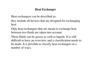
WHAT ARE HEAT EXCHANGERS? • Heat exchangers are one of the most common pieces of equipment found in all plants. • Heat Exchangers are components that allow the transfer of heat from one fluid (liquid or gas) to another fluid. • In a heat exchanger there is no direct contact between the two fluids. The heat is transferred from the hot fluid to the metal isolating the two fluids and then to the cooler fluid. • The mechanical design of a heat exchanger depends on the operating pressure and temperature .
APPLICATION OF HEAT EXCHANGERS Heat exchange is used every where around the human and its surroundings. Heat exchangers are used in many industries, some of which include: • Waste water treatment, • Refrigeration systems, • Wine-brewery industry, • Petroleum industry, • In aircraft industry to make the aircraft cool during the flights.
CLASSIFICATION OF HEAT EXCHANGER • Basic Classification • Regenerative Type • Recuperative Type • Classification Based On Fluid Flow • Liquid/Liquid • Liquid/Gas • Gas/Gas
Classification by flow arrangements • Concurrent – Flow in same direction • Thermodynamically poor • High thermal stresses since large temperature difference at inlet • Counter current- flow opposite to each other • Thermodynamically superior • Minimum thermal stresses • Maximum heat recovery • Least heat transfer area • Cross flow- Flow perpendicular to each other • In between the above • Space is important
TUBULAR HEAT EXCHANGER This type of heat exchanger are categorized in following types:- • Double Pipes heat Exchanger • Shell & Tube Heat Exchanger • Spiral Tube Heat Exchanger
DOUBLE-PIPE HEAT EXCHANGER Simplest type has one tube inside another - inner tube may have longitudinal fins on the outside
SHELL AND TUBE HEAT EXCHANGER • Shell and tube heat exchangers consist of a series of tubes. One set of these tubes contains the fluid that must be either heated or cooled. The second fluid runs over the tubes that are being heated or cooled so that it can either provide the heat or absorb the heat required. • A set of tubes is called the tube bundle and can be made up of several types of tubes: plain, longitudinally finned.
PLATE HEAT EXCHANGER This type of heat exchanger are categorized in following types:- • Plate & Frame Heat Exchanger • Spiral Heat Exchanger
PLATE & FRAME HEAT EXCHANGER • A plate type heat exchanger consists of plates instead of tubes to separate the hot and cold fluids. • The hot and cold fluids alternate between each of the plates. Baffles direct the flow of fluid between plates. • Because each of the plates has a very large surface area, the plates provide each of the fluids with an extremely large heat transfer area. • Therefore a plate type heat exchanger, as compared to a similarly sized tube and shell heat exchanger, is capable of transferring much more heat. • This is due to the larger area the plates provide over tubes.
SELECTION OF HEAT EXCHANGERS • Terminal Temperatures • Types of Fluids • Properties of Both Fluids • Flow Arrangement • Operating Pressure and Temperature • Pressure Drop • Heat Recovery • Fouling • Ease of Inspection, Cleaning, Repair & Maintenance • Materials of Construction • Cost of Heat Exchanger
Terminal Temperatures • Performance of Heat Exchanger depends on terminal temperatures • Heat Transfer Units (HTU) defined as ratio of * Temperature of one fluid * Mean temperature difference between the fluids • Plate heat exchanger > Tubular Heat Exchanger • Up to 4 HTU in case of Plate heat exchanger
Properties of Both Fluids • Heat Transfer Calculations • Pumping Calculations • Viscosity Low viscosity- Plate heat exchanger High viscosity- Scraped surface heat exchanger • Thermal conductivity • Density • Specific heat • Thermal diffusivity
Operating Pressure and Temperature Mechanical Design • Operating Pressure • Operating Temperature Problems of high operating temperature and pressure • Vibration • Fatigue • Thermal stresses, etc. Plate heat exchanger free from such problems however plate thickness and gasket material limit its application
Heat ExchangerT, 0CP, N/cm²Q, l/h • Plate heat exchanger260 21 50,00,00 • Double pipe540 70 no limit • Shell and tube540 105 no limit
Pressure Drop Important for • Pumping Cost - proportional to pressure drop • Heat Transfer Rate - proportional to pressure drop Heat Recovery • Conservation of energy- very important • Recovery of heat from used/waste process streams • Less than 50% in tubular heat exchangers • Up to 95% in plate heat exchanger
Fouling Deposition of solid material- poor conductor of heat * Decreases heat transfer * Decreases flow rate * Lead to corrosion * Loss of valuable materials * Affects the design and size of the unit * Affects the production runs Factors affecting fouling • Velocity- High velocity less fouling * Shearing force * Turbulence * Laminar layer thickness * Residence time • Surface temperature – important for heat sensitive liquids - small temperature difference required • Bulk fluid temperature – more fouling in less bulk temperature • Composition
Materials of Construction Material of construction depends on • Properties of the fluids such as heat sensitivity, fouling, corrosivity, • Operating temperature and pressure • Welding ease • Availability • Conformance to all applicable laws, codes and insurance requirements • Cost Materials Stainless steel Carbon steel Graphite Aluminum Titanium Hastalloy Gaskets Nitryl rubber Butyl rubber Teflon Compressed asbestos fibers
Overall Heat Transfer Coefficient • An essential requirement for heat exchanger design or performance calculations. • Contributing factors include convection and conduction associated with the • two fluids and the intermediate solid, as well as the potential use of fins on both • sides and the effects of time-dependent surface fouling. • With subscripts c and hused to designate the hotand cold fluids, respectively, • the most general expression for the overall coefficient is:
Counter-Flow Heat Exchanger: Evaluation of depends on the heat exchanger type. A Methodology for Heat Exchanger Design Calculations - The Log Mean Temperature Difference (LMTD) Method - • A form of Newton’s Law of Cooling may be applied to heat exchangers by • using a log-mean value of the temperature difference between the two fluids:
Parallel-Flow Heat Exchanger: • Note that Tc,ocan not exceed Th,ofor a PF HX, but can do so for a CF HX. • For equivalent values of UA and inlet temperatures, • Shell-and-Tube and Cross-Flow Heat Exchangers:
NTU METHOD The Number of Transfer Units (NTU) Method is used to calculate the rate of heat transfer in heat exchangers (especially counter current exchangers) when there is insufficient information to calculate the Log-Mean Temperature Difference(LMTD). • Assume negligible heat transfer between the exchanger and its surroundings • and negligible potential and kinetic energy changes for each fluid.
Negligible or no change in • Negligible or no change in • Assuming no l/v phase change and constant specific heats,
Heat exchangers are designed by the usual equation: • q = U*A*LMTD" • wherein: • U is the overall heat-transfer coefficient, • A is the area of the heat-exchange surface, and • LMTD is the Log Mean Temperature Difference.
Conclusions • General heat exchanger selection situation involves minimising cost subject to a long list of possible constraints • In general, robustness is a very important factor - shell-and-tube exchangers may not be the most efficient, but they score highly in this category