Design Team Project: Physical Design ( Layout )
170 likes | 894 Vues
Design Team Project: Physical Design ( Layout ). Kyungseok Kim. ELEC 7770 Advanced VLSI Design Lecturer: Dr. Vishwani D. Agrawal. Outline. ASIC Design Flow Physical Design: Automated IC Layout Design Objects: CPU, MUX (Alternative) Conclusion Reference. ASIC Design Flow.

Design Team Project: Physical Design ( Layout )
E N D
Presentation Transcript
Design Team Project: Physical Design ( Layout ) Kyungseok Kim ELEC 7770 Advanced VLSI Design Lecturer: Dr. Vishwani D. Agrawal
Outline • ASIC Design Flow • Physical Design: Automated IC Layout Design Objects: CPU, MUX (Alternative) • Conclusion • Reference
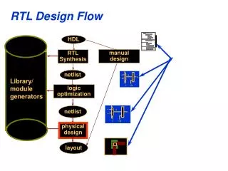
ASIC Design Flow Simulation Behavioral Model VHDL/Verilog Verify Behavior Synthesis DFT/BIST & ATPG Gate-Level Netlist Verify Function Full-custom IC Test vectors Transistor-Level Netlist Verify Function & Timing Standard Cell IC & FPGA/CPLD DRC & LVS Verification Physical Layout Map/Place/Route Verify Function & Timing IC Mask Data
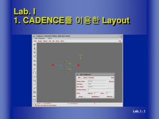
Layout Procedure: CPU CPU Schematic Symbol -TSMC 018um Tech. Foorplanning • Total Area = 157284512.0 um2 • Number of internal rows = 55 • Avg. instance height = 120.0 um • Avg. channel height = 120.0 um • Total connections (pins - nets) = 44099 • Internal zone width = 12008.0 um • Internal zone height = 13204.0 um • Aspect ratio = 0.93
Placing Std. Cells Connecting Ports • Bipartition for Placement • Number of core instances = 7601 • Number of signal nets = 8987 • Number of power nets = 2
Auto Routing Overflows Changing Options In Auto Route • Try another option for reducing overflows, but couldn’t remove all overflows!!! • Check Shorts: OK • Num of Overflows = 6678 • Number of global routing nodes: 157444 • Number of global routing arcs : 201136
Layout: MUX Automated Layout Flow MUX Gate Level 1. Extraction: Lumped R&C, Coupled C Post Simulation: Timing, Power 2. 3. Complete Layout 4. 5. 6. DRC OK! LVS OK!
Conclusion • Automated Layout not Perfect!!! - Overflows, Shorts, Dependent on Synthesis & Options in Floorplan and Route • Need communication in Synthesis Step - Reduce Overheads in Area and Net congestions • Post-layout Simulation for the Spec. • For Fabrication, Add Pads and Power • Generate GDS II
Reference • Dr. Nelson’s Lecture notes in ELEC6250 • Mentor IC Station User Manual • Mentor ADK Tutorial THANK YOU !!