Chapter 3 Physical Characteristics
1.51k likes | 3.15k Vues
Chapter 3 Physical Characteristics. Chapter 3 Physical Characteristics 3.1 Runways. Runway: A defined rectangular area on a land aerodrome prepared for the landing and take-off of aircraft. Number, siting and orientation of runways

Chapter 3 Physical Characteristics
E N D
Presentation Transcript
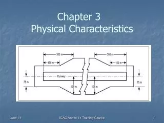
Chapter 3 Physical Characteristics ICAO Annex 14 Training Course
Chapter 3 Physical Characteristics3.1 Runways Runway: A defined rectangular area on a land aerodrome prepared for the landing and take-off of aircraft. Number, siting and orientation of runways Recommendation.— The number and orientation of runways at an aerodrome should be such that the usability factor of the aerodrome is not less than 95 per cent for the aeroplanes that the aerodrome is intended to serve. Recommendation.— The siting and orientation of runways at an aerodrome should, where possible, be such that the arrival and departure tracks minimize interference with areas approved for residential use and other noise sensitive areas close to the aerodrome in order to avoid future noise problems. [Note.- Guidance on how to address noise problems is provided in the Airport Planning Manual, Part 2, and in Guidance on the Balanced Approach to Aircraft Noise Management (Doc 9829).] ICAO Annex 14 Training Course
Chapter 3 Physical Characteristics3.1 Runways Number, siting and orientation of runways (continued) Factors affecting the sitting and orientation of runways: a)Type of operation - IMC, VMC - Day and night or only day. b) Climatological conditions - Wind statistics (speed and direction data for min. of 5 years ) for the calculation of usability factor; - Allowable cross wind components. ICAO Annex 14 Training Course
Chapter 3 Physical Characteristics3.1 Runways Number, siting and orientation of runways (continued) Factors affecting the sitting and orientation of runways (continued): c)Topography of the aerodrome site, its approaches, and surroundings, particularly: - compliance with the obstacle limitation surfaces; - current and future land use; - current and future runway lengths to be provided; - construction costs; and - possibility of installing suitable non-visual and visual aids for approach-to-land. ICAO Annex 14 Training Course
Chapter 3 Physical Characteristics3.1 Runways Number, siting and orientation of runways (continued) Factors affecting the sitting and orientation of runways (continued): d) Air traffic in the vicinity of the aerodrome, particularly: - proximity of other aerodromes or ATS routes; - traffic density; and - air traffic control and missed approach procedures. The number of runways to be provided in each direction depends on the number of aircraft movements to be catered to. ICAO Annex 14 Training Course
Chapter 3. Physical Characteristics3.1 Runways Location of threshold Recommendation.— A threshold should normally be located at the extremity of a runway unless operational considerations justify the choice of another location. [Note: If there are no obstacles penetrating above the approach surface.] ICAO Annex 14 Training Course
Chapter 3. Physical Characteristics3.1 Runways Location of threshold Recommendations.— When it is necessary to displace a threshold, either permanently or temporarily, from its normal location, account should be taken of the various factors which may have a bearing on the location of the threshold. Where this displacement is due to an unserviceable runway condition, a cleared and graded area of at least 60 m in length should be available between the unserviceable area and the displaced threshold. Additional distance should also be provided to meet the requirements of the runway end safety area as appropriate. Temporarly Displaced Threshold ICAO Annex 14 Training Course Permanently Displaced Threshold
Chapter 3. Physical Characteristics3.1 Runways Actual length of runways Primary runway - Runway(s) used in preference to others whenever conditions permit. Recommendation.— Except where a secondary runway is provided, the actual runway length to be provided for a primary runway should be adequate to meet the operational requirements of the aeroplanes for which the runway is intended and should be not less than the longest length determined by applying the corrections for local conditions to the operations and performance characteristics of the relevant aeroplanes. Secondary runway Recommendation.— The length of a secondary runway should be determined similarly to primary runways except that it needs only to be adequate for those aeroplanes which require to use that secondary runway in addition to the other runway or runways in order to obtain a usability factor of at least 95 per cent. ICAO Annex 14 Training Course
Chapter 3. Physical Characteristics3.1 Runways Actual length of runways ICAO Annex 14 Training Course
Chapter 3. Physical Characteristics3.1 Runways Runways with stopways or clearways Recommendation.— Where a runway is associated with a stopway or clearway, an actual runway length less than that determined for primary runway or secondary runway, as appropriate, may be considered satisfactory, but in such a case any combination of runway, stopway and clearway provided should permit compliance with the operational requirements for take-off and landing of the aeroplanes the runway is intended to serve. Runway with stopway and clearway ICAO Annex 14 Training Course
Chapter 3. Physical Characteristics3.1 Runways Width of runways Recommendation.— The width of a runway should be not less than the appropriate dimension specified in the following tabulation: a. The width of a precision approach runway should be not less than 30 m where the code number is 1 or 2. ICAO Annex 14 Training Course
Chapter 3. Physical Characteristics3.1 Runways Width of runways (continued) Factors affecting the width of runways are: a) deviation of an aeroplane from the centre line at touchdown; b) cross-wind conditions; c) runway surface contamination (e.g. rain, snow, slush or ice); d) rubber deposits; e) crab landing approaches used in cross-wind conditions; f) approach speed used; g) visibility; and h) Human factors. ICAO Annex 14 Training Course
Chapter 3. Physical Characteristics3.1 Runways Minimum distance between parallel runways Recommendation.— Where parallel non-instrument runways are intended for simultaneous use, the minimum distance between their centre lines should be: — 210 m where the higher code number is 3 or 4; — 150 m where the higher code number is 2; and — 120 m where the higher code number is 1. ICAO Annex 14 Training Course
Chapter 3. Physical Characteristics3.1 Runways Minimum distance between parallel runways Recommendation.— Where parallel instrument runways are intended for simultaneous use, the minimum distance between their centre lines should be: — 1 035 m for independent parallel approaches; — 915 m for dependent parallel approaches; — 760 m for independent parallel departures; — 760 m for segregated parallel operations [Manual of Simultaneous Operations on Parallel or Near-Parallel Instrument Runways (Doc 9643). ] ICAO Annex 14 Training Course
Chapter 3. Physical Characteristics3.1 Runways Slopes on runways Longitudinal slopes Recommendation.— The slope computed by dividing the difference between the maximum and minimum elevation along the runway centre line by the runway length (effective gradient) should not exceed: — 1 per cent where the code number is 3 or 4; and — 2 per cent where the code number is 1 or 2. ICAO Annex 14 Training Course
Chapter 3. Physical Characteristics3.1 Runways Slopes on runways Longitudinal slopes Recommendation.— Along no portion of a runway should the longitudinal slope exceed: — 1.25 per cent where the code number is 4, except that for the first and last quarter of the length of the runway the longitudinal slope should not exceed 0.8 per cent; — 1.5 per cent where the code number is 3, except that for the first and last quarter of the length of a precision approach runway category II or III the longitudinal slope should not exceed 0.8 per cent; and — 2 per cent where the code number is 1 or 2. ICAO Annex 14 Training Course
Chapter 3. Physical Characteristics3.1 Runways Slopes on runways (continued) Longitudinal slope changes Recommendation.— Where slope changes cannot be avoided, a slope change between two consecutive slopes should not exceed: — 1.5 per cent where the code number is 3 or 4; and — 2 per cent where the code number is 1 or 2. ICAO Annex 14 Training Course
Chapter 3. Physical Characteristics3.1 Runways Slopes on runways (continued) Longitudinal slope changes Recommendation.— The transition from one slope to another should be accomplished by a curved surface with a rate of change not exceeding: — 0.1 per cent per 30 m (minimum radius of curvature of 30,000 m) where the code number is 4; — 0.2 per cent per 30 m (minimum radius of curvature of 15,000 m) where the code number is 3; and — 0.4 per cent per 30 m (minimum radius of curvature of 7,500 m) where the code number is 1 or 2. ICAO Annex 14 Training Course
Chapter 3. Physical Characteristics3.1 Runways Sight distance Recommendation.— Where slope changes cannot be avoided, they should be such that there will be an unobstructed line of sight from: — any point 3 m above a runway to all other points 3 m above the runway within a distance of at least half the length of the runway where the code letter is C, D, E or F. — any point 2 m above a runway to all other points 2 m above the runway within a distance of at least half the length of the runway where the code letter is B; and — any point 1.5 m above a runway to all other points 1.5 m above the runway within a distance of at least half the length of the runway where the code letter is A. [Note.— Consideration will have to be given to providing an unobstructed line of sight over the entire length of a single runway where a full-length parallel taxiway is not available. Where an aerodrome has intersecting runways, additional criteria on the line of sight of the intersection area would need to be considered for operational safety.] ICAO Annex 14 Training Course
Chapter 3. Physical Characteristics3.1 Runways Slopes on runways (continued) Distance between slope changes Recommendation.— Undulations or appreciable changes in slopes located close together along a runway should be avoided. The distance between the points of intersection of two successive curves should not be less than: a) the sum of the absolute numerical values of the corresponding slope changes multiplied by the appropriate value as follows: — 30 000 m where the code number is 4; — 15 000 m where the code number is 3; and — 5 000 m where the code number is 1 or 2; or b) 45 m; whichever is greater. ICAO Annex 14 Training Course
Chapter 3. Physical Characteristics3.1 Runways Slopes on runways (continued) Distance between slope changes [Example] D for a runway of code number 3 should be at least: 15 000 (|x – y| + |y – z|) m Where: |x – y| being the absolute numerical value of x – y |y – z| being the absolute numerical value of y – z Assuming : x = + 0.01; y = –0.005; z = +0.005 then |x – y| = 0.015 |y – z| = 0.01 To comply with the specifications, D should be not less than: 15000 (0.015 + 0.01) m = 15000 × 0.025 = 375 m > 45m ICAO Annex 14 Training Course
Chapter 3. Physical Characteristics3.1 Runways Slopes on runways (continued) Transverse slopes Recommendation.— To promote the most rapid drainage of water, the runway surface should, if practicable, be cambered except where a single crossfall from high to low in the direction of the wind most frequently associated with rain would ensure rapid drainage. The transverse slopeshould ideally be: — 1.5 per cent where the code letter is C, D, E or F; and — 2 per cent where the code letter is A or B; but in any event should not exceed 1.5 per cent or 2 per cent, as applicable, nor be less than 1 per cent except at runway or taxiway intersections where flatter slopes may be necessary. For a cambered surface the transverse slope on each side of the centre line should be symmetrical. Recommendation.— The transverse slope should be substantially the same throughout the length of a runway except at an intersection with another runway or a taxiway where an even transition should be provided taking account of the need for adequate drainage. ICAO Annex 14 Training Course
Chapter 3. Physical Characteristics3.1 Runways Strength of runways Recommendation.— A runway should be capable of withstanding the traffic of aeroplanes the runway is intended to serve. Surface of runways • The surface of a runway shall be constructed without irregularities that would result in loss in friction characteristics or otherwise adversely affect the take-off or landing of an aeroplane. [Note 1.— Surface irregularities may adversely affect the take-off or landing of an aeroplane by causing excessive bouncing, pitching, vibration, or other difficulties in the control of an aeroplane.] • The surface of a paved runway shall be so constructed as to provide good friction characteristics when the runway is wet. ICAO Annex 14 Training Course
Chapter 3. Physical Characteristics3.2 Runway shoulders Runway shoulders (General) Recommendations.— • Runway shoulders should be provided for a runway where the code letter is D or E, and the runway width is less than 60 m. • Runway shoulders should be provided for a runway where the code letter is F. Width of runway shoulders Recommendation.— The runway shoulders should extend symmetrically on each side of the runway so that the overall width of the runway and its shoulders is not less than: — 60 m where the code letter is D or E; and — 75 m where the code letter is F. ICAO Annex 14 Training Course
Chapter 3. Physical Characteristics3.3 Runway turn pads Runway turn pad: A defined area on a land aerodrome adjacent to a runway for the purpose of completing a 180-degree turn on a runway. General • Where the end of a runway is not served by a taxiway or a taxiway turnaround and where the code letter is D, E or F, a runway turn pad shall be provided to facilitate a 180-degree turn of aeroplanes. Recommendation.— Where the end of a runway is not served by a taxiway or a taxiway turnaround and where the code letter is A, B or C, a runway turn pad should be provided to facilitate a 180-degree turn of aeroplanes. ICAO Annex 14 Training Course
Chapter 3. Physical Characteristics3.3 Runway turn pads General Recommendation.— The intersection angle of the runway turn pad with the runway should not exceed 30 degrees. Recommendation.— The nose wheel steering angle to be used in the design of the runway turn pad should not exceed 45 degrees. Runway turn pad for code E aircraft with 45 m width runway ICAO Annex 14 Training Course
Chapter 3. Physical Characteristics3.3 Runway turn pads General • The design of a runway turn pad shall be such that, when the cockpit of the aeroplane for which the turn pad is intended remains over the turn pad marking, the clearance distance between any wheel of the aeroplane landing gear and the edge of the turn pad shall be not less than that given by the following tabulation: Code letterClearance A 1.5 m B 2.25 m C 3 m if the turn pad is intended to be used by aeroplanes with a wheel base less than 18 m; 4.5 m if the turn pad is intended to be used by aeroplanes with a wheel base equal to or greater than 18 m. D, E & F 4.5 m Runway turn pad for code E Aircraft with 60 m width runway ICAO Annex 14 Training Course
Chapter 3. Physical Characteristics3.4 Runway strips Runway strip.A defined area including the runway and stopway, if provided, intended: a) to reduce the risk of damage to aircraft running off a runway; and b) to protect aircraft flying over it during take-off or landing operations. General • A runway and any associated stopways shall be included in a strip. Length of runway strips • A strip shall extend before the threshold and beyond the end of the runway or stopway for a distance of at least: — 60 m [ code number 2, 3 or 4]; — 60 m [code number 1 instrument runway]; and — 30 m [code number 1 non-instrument runway] . ICAO Annex 14 Training Course
Chapter 3. Physical Characteristics3.4 Runway strips Width of runway strips • A strip including a precision approach runway shall, wherever practicable, extend laterally on each side of the centre line of the runway and its extended centre line throughout the length of the strip, to a distance of at least: — 150 m [code number is 3 or 4]; and — 75 m [code number is 1 or 2]. Recommendation.— A strip should extend laterally on each side of the centre line of the runway and its extended centre line throughout the length of the strip, to a distance of at least: non-precision approach runwaynon-instrument runway — 150 m [ code number 3 or 4]; and - 75 m [code number 3 or 4]; — 75 m [ code number 1 or 2]. - 40 m [code number 2]; and - 30 m [ code number 1]. ICAO Annex 14 Training Course
Chapter 3. Physical Characteristics3.4 Runway strips Figure: Composition of Runway Strip ICAO Annex 14 Training Course
Chapter 3. Physical Characteristics3.4 Runway strips Objects on runway strips • No fixed object, other than visual aids required for air navigation purposes and satisfying the relevant frangibility requirement, shall be permitted on a runway strip: a) within 77.5 m of the runway centre line of a precision approach runway category I, II or III where the code number is 4 and the code letter is F; or b) within 60 m of the runway centre line of a precision approach runway category I, II or III where the code number is 3 or 4; or c) within 45 m of the runway centre line of a precision approach runway category I where the code number is 1 or 2. No mobile objectshall be permitted on this part of the runway strip during the use of the runway for landing or take-off. Recommendation.— An object situated on a runway strip which may endanger aeroplanes should be regarded as an obstacle and should, as far as practicable, be removed. ICAO Annex 14 Training Course
Chapter 3. Physical Characteristics3.4 Runway strips Grading of runway strips Recommendation.— That portion of a strip from the centre line of the runway and its extended centre line should provide a graded area for aeroplanes which the runway is intended to serve in the event of an aeroplane running off the runway within a distance of at least: Instrument runway Non-instrument runway — 75 m [code number is 3 or 4]; and — 75 m [code number is 3 or 4] — 40 m [code number is 1 or 2]; — 40 m [code number is 2]; — 30 m [code number is 1]. • The surface of that portion of a strip that abuts a runway, shoulder or stopway shall be flush with the surface of the runway, shoulder or stopway. Recommendation.— That portion of a strip to at least 30 m before a threshold should be prepared against blast erosion in order to protect a landing aeroplane from the danger of an exposed edge. ICAO Annex 14 Training Course
Chapter 3. Physical Characteristics3.4 Runway strips Grading of runway strips (continued) For a precision approach runway, it may be desirable to adopt a greater width of graded runway strips where the code number is 3 or 4. Figure A-3. Graded portion of a strip including a precision approach runway where the code number is 3 or 4 ICAO Annex 14 Training Course
Chapter 3. Physical Characteristics3.4 Runway strips Slopes on runway strips Longitudinal slopes Recommendation.— A longitudinal slope along that portion of a strip to be graded should not exceed: — 1.5 per cent [code number is 4]; — 1.75 per cent [code number is 3]; and — 2 per cent [code number is 1 or 2]. Longitudinal slope changes Recommendation.— Slope changes on that portion of a strip to be graded should be as gradual as practicable and abrupt changes or sudden reversals of slopes avoided. ICAO Annex 14 Training Course
Chapter 3. Physical Characteristics3.5 Runway end safety areas Runway end safety area (RESA) An area symmetrical about the extended runway centre line and adjacent to the end of the strip primarily intended to reduce the risk of damage to an aeroplane undershooting or overrunning the runway. General • A runway end safety area shall be provided at each end of a runway strip where: — the code number is 3 or 4; and — the code number is 1 or 2 and the runway is an instrument one. ICAO Annex 14 Training Course
Chapter 3. Physical Characteristics3.5 Runway end safety areas Dimensions of runway end safety areas • A runway end safety area shall extend from the end of a runway strip to a distance of at least 90 m. Recommendation.— A runway end safety area should, as far as practicable, extend from the end of a runway strip to a distance of at least: — 240 m where the code number is 3 or 4; and — 120 m where the code number is 1 or 2. • The width of a runway end safety area shall be at least twice that of the associated runway. Recommendation.— The width of a runway end safety area should, wherever practicable, be equal to that of the graded portion of the associated runway strip. ICAO Annex 14 Training Course
Chapter 3. Physical Characteristics3.5 Runway end safety areas Objects on runway end safety areas Recommendation.— An object situated on a runway end safety area which may endanger aeroplanes should be regarded as an obstacle and should, as far as practicable, be removed. Clearing and grading of runway end safety areas Recommendation.— A runway end safety area should provide a cleared and graded area for aeroplanes which the runway is intended to serve in the event of an aeroplane undershooting or overrunning the runway. [Note.— The surface of the ground in the runway end safety area does not need to be prepared to the same quality as the runway strip.] ICAO Annex 14 Training Course
Chapter 3. Physical Characteristics3.6 Clearways Clearway A defined rectangular area on the ground or water under the control of the appropriate authority, selected or prepared as a suitable area over which an aeroplane may make a portion of its initial climb to a specified height. Location of clearways Recommendation.— The origin of a clearway should be at the end of the take-off run available. ICAO Annex 14 Training Course
Chapter 3. Physical Characteristics3.6 Clearways Length of clearways Recommendation.— The length of a clearway should not exceed half the length of the take-off run available. Width of clearways Recommendation.— A clearway should extend laterally to a distance ofat least 75 mon each side of the extended centre line of the runway. ICAO Annex 14 Training Course
Chapter 3. Physical Characteristics3.6 Clearways Slopes on clearways Recommendation.— The ground in a clearway should not project above a plane having an upward slope of 1.25 per cent, the lower limit of this plane being a horizontal line which: a) is perpendicular to the vertical plane containing the runway centre line; and b) passes through a point located on the runway centre line at the end of the take-off run available. [Note.— Because of transverse or longitudinal slopes on a runway, shoulder or strip, in certain cases the lower limit of the clearway plane specified above may be below the corresponding elevation of the runway, shoulder or strip. It is not intended that these surfaces be graded to conform with the lower limit of the clearway plane nor is it intended that terrain or objects which are above the clearway plane beyond the end of the strip but below the level of the strip be removed unless it is considered they may endanger aeroplanes.] ICAO Annex 14 Training Course
Chapter 3. Physical Characteristics3.6 Clearways Slopes on clearways Recommendation.— Abrupt upward changes in slope should be avoided when the slope on the ground in a clearway is relatively small or when the mean slope is upward. In such situations, in that portion of the clearway within a distance of 22.5 m or half the runway width whichever is greater on each side of the extended centre line, the slopes, slope changes and the transition from runway to clearway should generally conform with those of the runway with which the clearway is associated. Objects on clearways Recommendation.— An object situated on a clearway which may endanger aeroplanes in the air should be regarded as an obstacle and should be removed. ICAO Annex 14 Training Course
Chapter 3. Physical Characteristics3.7 Stopways Stopway A defined rectangular area on the ground at the end of take-off run available prepared as a suitable area in which an aircraft can be stopped in the case of an abandoned take off. Width of stopways • A stopway shall have the same width as the runway with which it is associated. ICAO Annex 14 Training Course
Chapter 3. Physical Characteristics3.7 Stopways Slopes on stopways Recommendation.— Slopes and changes in slope on a stopway, and the transition from a runway to a stopway, should comply with the specifications of slopes for the runway with which the stopway is associated except that: a) the limitation of a 0.8 per cent slope for the first and last quarter of the length of a runway need not be applied to the stopway; and b) at the junction of the stopway and runway and along the stopway the maximum rate of slope change may be 0.3 per cent per 30 m (minimum radius of curvature of 10 000 m) for a runway where the code number is 3 or 4. ICAO Annex 14 Training Course
Chapter 3. Physical Characteristics3.7 Stopways Strength of stopways Recommendation.— A stopway should be prepared or constructed so as to be capable, in the event of an abandoned take-off, of supporting the aeroplane which the stopway is intended to serve without inducing structural damage to the aeroplane. Surface of stopways Recommendations.— • The surface of a paved stopway should be so constructed as to provide a good coefficient of friction to be compatible with that of the associated runway when the stopway is wet. • The friction characteristics of an unpaved stopwayshould not be substantially less than that of the runway with which the stopway is associated. ICAO Annex 14 Training Course
Chapter 3. Physical Characteristics3.9 Taxiways Taxiway A defined path on a land aerodrome established for the taxiing of aircraft and intended to provide a link between one part of the aerodrome and another, including: a) Aircraft stand taxilane. A portion of an apron designated as a taxiway and intended to provide access to aircraft stands only. b) Apron taxiway. A portion of a taxiway system located on an apron and intended to provide a through taxi route across the apron. c) Rapid exit taxiway. A taxiway connected to a runway at an acute angle and designed to allow landing aeroplanes to turn off at higher speeds than are achieved on other exit taxiways thereby minimizing runway occupancy times. ICAO Annex 14 Training Course
Chapter 3. Physical Characteristics3.9 Taxiways Taxiways on aprons ICAO Annex 14 Training Course
Chapter 3. Physical Characteristics3.9 Taxiways Taxiway General Recommendations.— • Taxiways should be provided to permit the safe and expeditious surface movement of aircraft. • Sufficient entrance and exit taxiways for a runway should be provided to expedite the movement of aeroplanes to and from the runway and provision of rapid exit taxiways considered when traffic volumes are high. ICAO Annex 14 Training Course
Chapter 3. Physical Characteristics3.9 Taxiways General • As of 20 November 2008, the design of a taxiway shall be such that, when the cockpit of the aeroplane for which the taxiway is intended remains over the taxiway centre line markings, the clearance distance between the outer main wheel of the aeroplane and the edge of the taxiway shall be not less than that given by the following tabulation: Code letterClearance A 1.5 m B 2.25 m C 3 m if the taxiway is intended to be used by aeroplanes with a wheel base less than 18 m; 4.5 m if the taxiway is intended to be used by aeroplanes with a wheel base equal to or greater than 18 m. D, E, F 4.5 m [Note 1.— Where the code letter is F and the traffic density is high, a wheel-to-edge clearance greater than 4.5 m may be provided to permit higher taxiing speeds.] Remarks: Till 19 November 2008 it remains as Recommendation. ICAO Annex 14 Training Course
Chapter 3. Physical Characteristics3.9 Taxiways Width of taxiways Recommendation.— A straight portion of a taxiway should have a width of not less than that given by the following tabulation: Code letterTaxiway width A 7.5 m B 10.5 m C 15 m if the taxiway is intended to be used by aeroplanes with a wheel base less than 18 m; 18 m if the taxiway is intended to be used by aeroplanes with a wheel base equal to or greater than 18 m. D 18 m if the taxiway is intended to be used by aeroplanes with an outer main gear wheel span of less than 9 m; 23 m if the taxiway is intended to be used by aeroplanes with an outer main gear wheel span equal to or greater than 9 m. E 23 m F 25 m ICAO Annex 14 Training Course
Chapter 3. Physical Characteristics3.9 Taxiways Taxiway curves Recommendation.— • Changes in direction of taxiways should be as few and small as possible. • The radii of the curves should be compatible with the manoeuvring capability and normal taxiing speeds of the aeroplanes for which the taxiway is intended. • The design of the curve should be such that, when the cockpit of the aeroplane remains over the taxiway centre line markings, the clearance distance between the outer main wheels of the aeroplane and the edge of the taxiway should not be less than those specified earlier. ICAO Annex 14 Training Course