Download
1 / 43
440 likes | 912 Vues
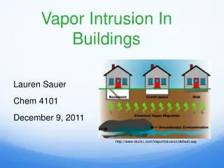
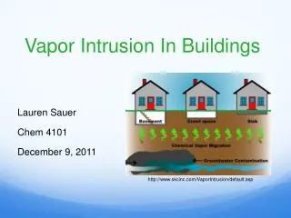
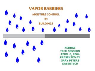
VAPOR BARRIERS MOISTURE CONTROL IN BUILDINGS. ASHRAE TECH SESSION APRIL 8, 2004 PRESENTED BY GARY PETERS GREENTECH. VAPOR BARRIERS versus AIR BARRIERS Air Barriers prevent air movement while allowing moisture to pass through. Air barriers must be carefully sealed at all penetrations.

E N D
VAPOR BARRIERSMOISTURE CONTROLINBUILDINGS ASHRAE TECH SESSION APRIL 8, 2004 PRESENTED BY GARY PETERS GREENTECH
VAPOR BARRIERS versus AIR BARRIERS Air Barriers prevent air movement while allowing moisture to pass through. Air barriers must be carefully sealed at all penetrations. Vapor Barriers are used to control the flow of moisture through the building envelope’ .
Classes of Vapor Barriers and Vapor Retarders • The unit of measurement for water vapor permeability is the “perm”. • Three general classes of materials, based on permeability. • Vapor Impermeable – “Vapor Barriers” • 0.1 perms or less: Class I • 1.0 perms or less: Class II • Typical Materials: Rubber membranes; polyethylene film; glass; aluminum foil; sheet metal; some vinyl wall covering; foil- faced insulating sheathings • Vapor Semi-permeable – “Vapor Retarders” • 10 perms or less: Class III • Typical Materials: Plywood; unfaced expanded polystyrene (EPS); asphalt impregnated building paper; many latex based paints; paper and bitumen facing on fiberglass batt insulation • Vapor Permeable – “Breathable” • More than 10 perms • Typical Materials: Unpainted gypsum board; unfaced fiberglass insulation; lightweight asphaltimpregnated building paper; exterior gypsum sheathing; “housewraps”
Permeability 0.000 Water vapor transmission of Zero Perm in a flat condition is 0.000 grams per hour per square meter. After sharp creasing under 25-lb. pressure at 3/4'' intervals with creases at right angles forming crease intersections at 3/4'' intervals permeance is only 0.0134 grams per 100 sq. in. per 24 hrs. Joints sealed with 1 1/2'' Zero Perm Pressure Sensitive Tape and joints overlapped 1 1/2'' and sealed with Alumiseal Zero Perm Adhesives also exhibit a permeance of 0.000 grams per lineal inch per 24 hrs. Test sources available on request. UL Listing An important feature of Zero Perm is its performance in Underwriters Laboratories (UL) Surface Burning Characteristics Test (UL 723). Zero Perm is UL listed as follows: Flame spread 5 Fuel contributed 0 Smoke developed 5Note: The numerical flame spread ratings are not intended to reflect hazards presented by this or any other material under actual fire conditions. Flex Life Zero Perm's outer mylar layer can endure over 20,000 cycles of flexing without failure.
Thermal Stability Zero Perm remains flexible and stable over a temperature range from -100° F to +300° F Tensile Strength Has a tensile strength of over 25,000 psi, a bursting strength of 96.6 psi. It requires a 23,500 psi stress at 130% strain to cause an elongation break in the mylar outer laminate Inertness Zero Perm exhibits excellent inertness to water, salt spray, wet mortar, caustics plus chemical solvents, oils, greases and can be safely applied to masonry walls. Resistance to Abrasion Zero Perm has extremely high resistance to abrasion.
Vapor Transportation Mechanisms Capillary Action:Wetted surfaces Air transported moisture – Air transported moisture can be more significant than vapor diffusion. Vapor Diffusion: Second law of thermodynamics. Moisture will flow by diffusion because of a concentration gradient as well as a temperature gradient. “More to less” “Warm to cold” Moisture control generally requires both an air barrier and a vapor barrier. Uncontrolled air infiltration into walls because of inadequate air barriers can cause catastrophic problems
LOCATION of VAPOR BARRIERS and AIR BARRIERS • COLD CLIMATES • Goal is to make it as difficult as possible for the building assemblies to get wet from the interior. • Install air barriers and vapor barriers on the interior building assemblies. Let the building assemblies dry to the exterior by installing the vapor permeable materials toward the exterior. • HOT and HUMID CLIMATES • Goal is to make it as difficult as possible for the building assemblies to get wet from the exterior. • Install air barriers and vapor barriers on the exterior of the building assemblies. Let the building assemblies dry to the interior. Impermeable interior wall coverings must be avoided. The interior space must be maintained at a slight positive pressure with conditioned/dehumidified air to limit infiltration • MIXED CLIMATES COMPLICATED!!!!!!!!!!!!!!!!!!!!!!!!!!!!!!!!!!!! • Flow through approach: Use permeable materials on both interior and exterior. This requires both air pressure control and interior moisture control. • Install the vapor barrier in the approximate thermal “middle” of the wall with insulating sheathing on the exterior. The air barrier can be toward the interior or the exterior. Air pressure control and interior moisture control must be utilized.
TRANSMISSION RATES FOR TYPICAL BUILDING MATERIALS MATERIALTRANSMISSION RATE ( grams/hr./sq. meter) Perms Concrete Block 2.40 Gypsum Board 50.00 Plywood 1.90 Plaster 15.00 Glazed Tile 0.12 Vapor Retarder Paint 0.45 Semi-Gloss Acrylic 6.61 Polyethylene, 6mil 0.06 Polyethylene, 10 mil 0.03 Mylar/Aluminum 0.00 (Zero-Perm)
VAPOR BARRIERS and MOLD Moisture accumulates in the building envelope when the rate of moisture entry exceeds the rate of moisture removal. When moisture accumulation exceeds the ability of the materials to store the moisture, moisture problems result. Moisture storage capacity of materials depends on Time – Dwell time, or drying time Temperature Material Properties
EXAMPLES: In a house the average 2000 square foot house, the wood based sheathing and wood framing have an equilibrium moisture content of 5% to 6%. The walls have a hygric buffer capacity of 10% which equals approximately 50 gallons of water for the 4,000 to 5,000 pounds of wood product in the exterior walls. When the moisture content exceeds 16% by weight, mold will develop. That same house with steel framing and gypsum sheathing has a hygric buffer capacity of 5 gallons of water. A highly insulated wall has a high dwell time and poor drying characteristics. Very small amounts of water will cause problems because of the low hygric buffer capacity and the slow drying times. A house with masonry exterior walls and masonry cladding has a hygric buffer capacity of 500 gallons.
Steel Frame with Gypsum Sheathing Approx. 5 gallons (19L) Wood Frame with Wood Sheathing Approx. 50 gallons (189L) Masonry Wall Approx. 500 gallons (1892L) HYDRIC BUFFER CAPACITY FOR 2000 SQ. FT HOUSE
MOISTURE CONTROL IN BUILDINGS • TO MINIMIZE THE RISK OF • MOISTURE DAMAGE • I. Control Moisture Entry • Repair roof leaks, flashing, floors, foundations • Prevent wind driven rain fro entering the wall assembly • Direct rain and ground water away from building • Airflow retarder must resist pressure from wind, stack effect, and mechanical ventilation
Control Water Vapor Migration • Limit water entry into building envelope with proper airflow retarders and vapor retarders • 6 to 22% of air leakage at windows and doors • 18 to 50% of air leakage occurs through walls • 3 to 30% of air leakage occurs through ceilings
Control Moisture Accumulation • Control dominate direction of air flow • In climates requiring cooling, maintain the building at light positive pressure to prevent unconditioned, humid air from entering the envelope. • In climates requiring heating, maintain a neutral building pressure.
Control the Removal of Moisture • Provide envelope system that allows assembly to dry to either the exterior or the interior, depending on climate. • Provide dedicated, conditioned low moisture content make up air systems • Maintain slight positive pressure • Leakage of saturated air from building AC system can migrate into building envelope assemblies.
Classic Example of a Connecticut Wall System Building: Upper range hotel Walls: Vinyl Wall Covering, Gypboard, Vapor Barrier,Fiberglass Insulation, Sheathing,EIFES and Brick Flashing: Poorly installed Guest Room AC: PTAC Thru the wall, exhaust fan in Bathroom Corridor AC: Standard split system air conditioning units delivering conditioned outside at saturated conditions Complaint: Employee complaints, very high rate of sick days, some customers complained odors Findings: Rooms were some times positively pressured, sometimes negative. Air leakage into building envelope around PTACS. The gyp board and sheathing facing the interior of the wall cavity were 100% covered with black and green mold
The Brick Veneer Wall Problem • Rain wetted followed by solar radiation • The sun drives the moisture inward. Ideally, the vapor barrier would be behind the brick veneer to stop the inward flow. That does not work in a cold climate. • In a cold climate, the vapor barrier is typically on the “warm” side. Moisture can get trapped in the wall cavity for extended periods of time. • Possible Solutions • Vapor Barrier behind the bricks and a vapor retarder on the inside • Semi-vapor permeable insulating sheathing on the outside wall, insulation to provide sufficient thermal resistance to elevate the temperature of the condensing surface during the heating season and a vapor permeable interior finish to allow drying to the interior • There are no easy answers! • There is no one correct solution!
ENVIRONMENTALLY CONTROLLED SPACES VAPOR BARRIER IMPACT ON EQUIPMENT SIZING AND OPERATING COST
ASHRAE TECHNICAL SESSION PRESENTATION “VAPOR BARRIERS” DEHUMIDIFICATION Select and size a dehumidification system for a site constructed with and without a vapor barrier. Project the equipment (first) cost and the operating cost for the dehumidification system with each construction method. ASSUMPTIONS: Hours/per year of dehumidification: 4,000 Electric Utility Rate: $0.11/Kwhr. Space Dimensions: 50’ x 50’ x 9’ high, all interior surrounded by conditioned space, 24” ceiling plenum and roof above. Room conditions to be maintained: 64 degrees db/35% RH Room Load – Constant: 375,000 Btu/hr Sensible 225,000 Btu/hr Latent 600,000 Btu/hr Total Room surrounding conditioned space: 80 degrees db / 50% RH CONDITION “A” Walls constructed with 5/8” sheetrock on both sides, no insulation and no vapor barrier Ceiling, standard acoustical tiles Roof, insulated with no vapor barrier CONDITION “B” Walls constructed with 5/8” sheetrock on both sides, no insulation, and with a vapor barrier with a transmission rate of 0.000 grams/hr/sq. meter. The vapor barrier is installed under the sheetrock on the conditioned space side of the wall. Ceiling, acoustical tiles with a vapor barrier with a transmission rate of 0.04 grams/hr/sq. meter Roof, insulated with no vapor barrier
BRY-AIR, INC. ROUTE 37-W SUNBURY, OH 43074 TEL (740) 965-2974 FAX (740) 965-5470 The choice for desiccant dehumidification CONDITIONED SPACE 22,500 FT.3 64°FDB 35% RH 31 GR/LB RETURN AIR600 CFM64°FDB31 GR/LB DEH PROCESS DX AFTER-COOLING29.2 MBH 3 TR 600 CFM 56°FDB 7.9 GR/LB 600 CFM 97°FDB 7.9 GR/LB 600 CFM 64°FDB 31 GR/LB 30% FILTER 30% FILTER REACT REACT EXHAUST 200 CFM 284°FDB 200 CFM 84°FDB REACT FAN FLOW DIAGRAM (No Vapor Barrier) Electric Re-activation 12.7 kw DEHUMIDIFIER Approximate Full Connected Load: 22.6kW
BRY-AIR, INC. ROUTE 37-W SUNBURY, OH 43074 TEL (740) 965-2974 FAX (740) 965-5470 The choice for desiccant dehumidification CONDITIONED SPACE 22,500 FT.3 64°FDB 35% RH 31 GR/LB RETURN AIR300 CFM64°FDB31 GR/LB DEH PROCESS DX AFTER-COOLING29.2 MBH 3 TR 300 CFM 49°FDB 7.9 GR/LB 300 CFM 97°FDB 7.9 GR/LB 300 CFM 64°FDB 31 GR/LB 30% FILTER 30% FILTER REACT REACT EXHAUST 100 CFM 284°FDB 100 CFM 84°FDB REACT FAN FLOW DIAGRAM With Vapor Barrier DEHUMIDIFIER Electric Re-activation 6.3 kw Approximate Full Connected Load: 12.2kW
EFFECT OF VAPOR BARRIER ON DEHUMIDFICATION COSTS Room size: 50’ x 50’ x 9’ Room design: 64°F DB / 35% RH Surrounding conditions: 80°F DB / 50% RH Hours/per year of operation: 4,000 Electric Utility Rate: $0.11/Kwhr Assuming a constant latent load in the space of 8,840 gr/hr from the 5 door openings/hour of a 7’x3’ door and moderate work done by 5 occupants in the space. This equates to a total internal latent load of 1330 BTUH (excluding infiltration). Assuming a constant sensible load in the space of 2 BTUH per square foot, over 2500 sq ft of the space the total internal sensible load will be 5000 BTUH.
CONDITION “A” (NO VAPOR BARRIER) Using 0.9 as the F4 factor in the dehumidification calculation sheet for no vapor barrier, the infiltration load is 48,566 gr/hr. The total latent load is 57,406 gr/hr and the required airflow is 600 scfm. Reactivation energy required is 43,200 BTUH or 12.7 KW. Cooling (3 TR condensing unit) energy required is 5.9 KW. Total energy required (including motors) is 22.6 KW. First cost of equipment is approximately $20,000 USD. Operating cost of equipment is $9,944 USD yearly.
CONDITION “B” (WITH VAPOR BARRIER) Using 0.35 as the F4 factor in the dehumidification calculation sheet for room with vapor barrier, the infiltration load is 18,887 gr/hr. The total latent load is 27,727 gr/hr and the required airflow is 300 scfm. Reactivation energy required is 21,600 BTUH or 6.3 KW. Cooling (2 TR condensing unit) energy required is 2.9 KW. Total energy required (including motors) is 12.2 KW. First cost of equipment is approximately $13,000 USD. Operating cost of equipment is $5,368 USD yearly.
CONTROLLED ENVIRONMENTAL SPACE VAPOR BARRIER PAYBACK NO CORRECT ITEM VAPOR BARRIER VAPOR BARRIER SAVINGS Equipment Costs $20,000 $13,000 $7,000 Operating Costs $ 9,944 $ 5,368 $4,576 Cost to properly vapor treat the space……………..$1,200
ASHRAE TECHNICAL SESSION PRESENTATION “VAPOR BARRIERS” HUMIDIFICATION Select and size a humidifier system for a site constructed with and without a vapor barrier. Project the equipment (first) cost and the operating cost for the humidification system with each construction method. ASSUMPTIONS: Hours / year for humidification: 4,000 Electric Utility Rate: $0.11/Kwhr Space Dimensions: 50’ x 50’ x 9’ high, all interior surrounded by conditioned space, 24” ceiling plenum and roof above. Room Conditions to be maintained: 72 degrees db/ 50% R.H. Room Load - Constant: 672,000 Btu/hr Sensible 50,000 Btu/hr Latent 722,000 Btu/hr Total Room surrounding conditioned space: 76 degrees db / 30% RH CONDITION “A”: Walls constructed with 5/8” sheetrock on both sides, no insulation and no vapor barrier Ceiling, standard acoustical tiles Roof, insulated with no Vapor Barrier CONDITION B: Walls constructed with 5/8” sheetrock on both sides, no insulation, and with a vapor barrier with a transmission rate of 0.000 grams/hr/sq. meter. The vapor barrier is installed under the sheetrock on the conditioned space side of the wall. Ceiling, acoustical tiles with a vapor barrier with a transmission rate of: 0.04 grams/hr/sq. meter Roof, insulated with no vapor barrier
HUMIDIFIER SELECTION and OPERATING COST Calculated humidifier load with “perfect” vapor barrier………9# / hr; 3.0 kW Load with no vapor barrier – many variable – Probably…… 22# / hr; 7.3kW Rule of thumb: 3# / hr / kw Savings with vapor barrier………………………………………….4.0kW / hr 4.0kW / hr x 3500 hrs x $0.11 / kwhr = $1,540.00 Cost to vapor treat the space………………………………………$1,200.00 Use available manufacturer’s software to calculate the load
Neptronic HumidisoftHumidification Software is an indispensable tool for anyone who is involved in the design, selection or installation of humidification systems.Consulting Engineers are able to quickly calculate humidification loads, select humidifiers, select steam dispersion systems, generate calculation reports, produce exportable product schedules and wiring diagrams.Contractors can quickly obtain dimensional data, installation information and much more. Humidisoft Humidification Design Software Features: • General: • English or French language • Metric (SI) or English (US) units • Easy to use, visual help • Auto-update feature to ensure latest version is easily available • All reports are exportable to rich text and PDF formats for easy transfer of information
Technical: • Design criteria (temperature, humidity and altitude) for most major cities already in the software • Load calculations can be done based on infiltration, mechanical or economizer fresh air exchange • Best-cost humidifier selection based on calculated load • Dispersion distance calculation • Dispersion manifold selection • Calculation report • Detailed option selection chart • Integrated product schedule • Complete submittal drawings including PROJECT AND PRODUCT SPECIFIC information, installation, dimensions and wiring information
RESOURCES Alumiseal Corporation ASHRAE FUNDAMENTALS HANDBOOK Bry-Air Corporation Building Science Corporation, Joseph Lstiburek, PhD Lincoln Electric System Louisiana State University, Dept of Natural Resources University of Wisconsin – Cooperative Education