Download
1 / 20
200 likes | 456 Vues
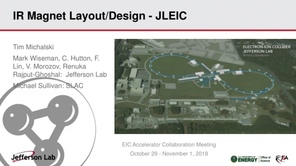
IR Magnet Layout/Design - JLEIC. Tim Michalski Mark Wiseman, C. Hutton, F. Lin, V. Morozov , Renuka Rajput-Ghoshal: Jefferson Lab Michael Sullivan: SLAC. EIC Accelerator Collaboration Meeting October 29 - November 1, 2018. Importance Defined by the Jones Report.

E N D
IR Magnet Layout/Design - JLEIC Tim Michalski Mark Wiseman, C. Hutton, F. Lin, V. Morozov, Renuka Rajput-Ghoshal: Jefferson Lab Michael Sullivan: SLAC EIC Accelerator Collaboration Meeting October 29 - November 1, 2018
Importance Defined by the Jones Report • The IR magnet design and construction challenge has been recognized by the Report of the Community Review of EIC Accelerator R&D for the Office of Nuclear Physics Fall 2018 EIC Accelerator Collaboration Meeting
Interaction Region (IR) Magnet Design Verification (FY’17 Base R&D) • Description • There are 12 Final Focus Quadrupole (FFQ) and 2 Spectrometer Dipole (SD) high field, large aperture superconducting magnets located within the JLEIC interaction region. • Baseline parameters have been defined. • Modeling, simulation, and 3D layouts are required to verify designs which satisfy sound magnet design, beam transport and beam physics requirements, and detector background requirements. • Goals • Each of the IR magnets is designed and analyzed in 3D TOSCA to verify the design is feasible and required performance parameters are attainable. • 3D models representing the magnet designs are added to the JLEIC layout for verifying space allocation, mechanical support, and cryostat placement. • Beam studies and detector background simulations of the resultant designs will define any required changes. • Iterations on designs will be performed such that all involved groups agree on an acceptable design solution. • Deliverables • 3D TOSCA models for all magnet designs shall be generated to demonstrate field strength, magnet size, impact to the adjacent beam, magnet current, etc. • 3D CAD models for all magnet designs shall be generated to demonstrate space allocation, structural support, and IR vacuum space for background simulations. • Iterations of specific magnet designs will be performed as required. Fall 2018 EIC Accelerator Collaboration Meeting
What part of JLEIC are we looking at? Fall 2018 EIC Accelerator Collaboration Meeting
Outline • Interaction Region Overview Layout • Magnet Design • Magnet Optimization • Magnet-Magnet Interactions • Beam Transport Area and Cryostat Designs • Summary and Outlook Fall 2018 EIC Accelerator Collaboration Meeting
Interaction Region (IR) Overview Layout • The design thus far considered six distinct areas of magnets • Detector Solenoid ( 4 m) • SB1 dipole (1.5 m) • SB2 dipole (~4.6 m) • Ion entrant side cryostat (~8.7 m) • Electron entrant cryostat, between the Detector Solenoid and SB1 (~2.6 m) • Ion down beam cryostat between the two spectrometer dipoles (~10.4 m) • This talk will focus on the three beam transport sections, 4-6 ~32 m Ion Up Beam Ion Down Beam Electron Entrant i e 3 4 5 6 2 1 Fall 2018 EIC Accelerator Collaboration Meeting
Magnet Design – Ion Magnet Parameters • All 6 QFFB magnets require Nb3Sn due to peak field • 3 downstream magnets are most challenging due to aperture size • Each FFQ has a corresponding skew quadrupole. FFQ fields are too high to allow nesting in the three down beam quadrupoles. Fall 2018 EIC Accelerator Collaboration Meeting
Magnet Design – Electron Magnet Parameters Each of the quadrupoles will need a corresponding skew quadrupole. Fall 2018 EIC Accelerator Collaboration Meeting
Magnet Design • All of the magnets for both the ion and electron beam lines are based on cold bore designs. • This is primarily to lower the field requirements on the ion beam quadrupoles. • The magnets in the electron beam line could be either warm or cold bore. • The cold bore designs in the electron line do reduce the radial space needed which is a plus as you get closer to the IP. • Expectation is to use existing, proven conductor – LARP for Nb3Sn, Standard Rutherford cable for NbTi Fall 2018 EIC Accelerator Collaboration Meeting
Magnet Design – Electron and Ion Upstream Quad Peak Field in Upstream Ion Quad (QFFB2_US) The conductor is envisaged to be stranded, Nb3Sn cable with 20-30 strands per cable using 0.7 mm diameter strands. This type of Nb3Sn conductor is also being used for the LARP magnets. Peak Field in Electron Quad The coils will be operated at 4000 A and will use 9.73 mm x 1.2 mm Rutherford cable. Fall 2018 EIC Accelerator Collaboration Meeting
Magnet Design – Ion Downstream Quad Coil field in QFFB2 Before Optimization Von-Mises Stress in QFFB2 Before Optimization First Order Optimization brings the peak coil field down from 10.3 T to 8.8 T. Fall 2018 EIC Accelerator Collaboration Meeting
Magnet Design – Skew Quad, Solenoid, Corrector Magnet • Peak field in Skew quad is 4.6 T(this will change after optimization) • Peak Field in the Solenoid is 6T (this will change after including the shielding) • Peak Field in the Corrector is 3.5 T (this will change after finalizing the specification and conductor) Fall 2018 EIC Accelerator Collaboration Meeting
Magnet-Magnet Interaction • In order to study the magnet-magnet interactions, the following combinations were selected for the initial study: • QFFUS1 with Ion beam line • QFFB2 with electron beam line • QFFB1, QFFUS3 and EL SOL_ANTI_US • QFFDS2 and QFFB1_US QFFUS1- (i) ion beam tube wrapped with 5 mm mild steel passive shield (ii) the vacuum vessel for the QFFUS1 is assumed to be made of mild steel, and (iii) a combination of the above two options Fall 2018 EIC Accelerator Collaboration Meeting
Magnet-Magnet Interaction • In order to study the magnet-magnet interactions, the following combinations were selected for the initial study: • QFFUS1 with Ion beam line • QFFB2 with electron beam line • QFFB1, QFFUS3 and EL SOL_ANTI_US • QFFDS2 and QFFB1_US QFFB2- This magnet is simulated with return yoke thicknesses of 200 mm and 250 mm around the magnet, active shield around the magnet, a combination of iron yoke and an active shield coil Corrector magnet and 2 transport quadrupoles have not been simulated with QFFB2 for now Fall 2018 EIC Accelerator Collaboration Meeting
Ion Up Beam Area • ‘Z’ spacing of the magnets • Reserve 10 cm on each magnet end for field optimization, coil clamps, etc. • Reserve 30 cm for a warm to cold transition and 10 cm for a bellows at the end of the cryostats • Eighteen plus multipole correctors and shielding coils in a single ~8.7 m long cryostat • Three identical quads in electron line with nested skew quads • Three quads in ion line with nested skew quads • 1.2 m solenoid in each line (same design) • Two horizontal/vertical correctors in ion line near IP i Quad with nested skew quad • Both the cryostat and cold mass will be supported in at least three locations with a minimum of twelve typical support rods on the cold mass. • A thermal shield will be included inside of the vacuum vessel and surround the entire cold mass. • The cryogenic feed and magnet lead can will be positioned on one side of the cryostat away from the detector elements. e 1st dipole in Compton chicane ~8.7 m AASOLEUS QFFB3_US QFFB2_US QFFB1_US IPUSCORR1 IPUSCORR2 QFFDS2 QFFDS1 QFFDS3 EL SOL ANTI_DS Fall 2018 EIC Accelerator Collaboration Meeting
Electron Entrant Area • Four magnets plus shield coils in a ~2.6 m long cryostat • The cryostat will be tapered near the IP to avoid interference with the ion vacuum beam line and to allow for the maximum acceptance angle for the detector elements. • To avoid interference with the ion beam vacuum line, the vacuum vessel and thermal shield will centered eccentrically from the cold mass. • The warm to cold transition will extend into the detector dipole on one end and stop just short of the detector solenoid on the other. e beam ion beam • Intercept needed for synchrotron radiation in the electron line • We can move the synchrotron intercept outside of the warm to cold transition area • The cold bore heat loads appear to be acceptable ~2.6 m QFFUS1 QFFUS2 Detector Solenoid SB1 Fall 2018 EIC Accelerator Collaboration Meeting
Ion Down Beam Area Fourteen magnets plus multipole correctors and shield coils in a single ~10.4 m long cryostat • Transport quads are superconducting as warm magnets impinge on the radial space of the ion beamline – same design as the other electron FFQs • Three large bore, high strength quads in ion line (QFFB1, 2, 3) • Large bore solenoid in ion beam line (AASOLEDS) • Four separate skew quads in ion line – (QFFDS01S, 02S, 22S, 03S) • Looking at shielding design and magnet support structure near the QFFB2 magnet e Warm Quad Girder i SB1 QFFUS3 EL SOL ANTI_US Transport Quads ~10.4 m QFFB1 QFFB2 AASOLEDS QFFB3 QFFDS01S QFFDS02S QFFDS22S QFFDS03S SB2 Fall 2018 EIC Accelerator Collaboration Meeting
Integration with detector dipole • Designs of beamlines will be closely coupled to the SB1 spectrometer dipole design • Two H/V correctors (IPDSCORR1&2) still to be placed in ion beam line • Combined dipole/corrector specification and location selection in progress • In the preliminary designs both cryostat beam lines extended into the SB1 • This will probably change as we incorporate the new corrector requirements • Physics detectors are also desired between this magnet bore and the vacuum beam line. • The adjacent electron beam line will also require shielding from this combined function magnet. Warm to cold transitions and RF bellows inside SB1 1.5m SB1 Fall 2018 EIC Accelerator Collaboration Meeting
Summary and Outlook • A thorough first layout and magnet analyses have been performed on all IR magnets. • Further review of the shielding requirements is underway. • Cryostat definition is also underway in order to outline space available for detectors. • Additional cryostat detail is required to insure magnets can be supported, accommodate cooldown, withstand magnetic loads, and integrate into detector space designs • Continue work on shielded bellows concepts that can be used for beam impedance studies • Possibly add shielded bellows inside the cryostats to ease assembly and alignment. • Work on shielded vacuum pump designs that can be used in the area that would be compatible with the physics detectors. • A separate group is studying the vacuum requirements within the IR needed to limit the impact from background noise on the detectors. • The information presented here is for s = 65 GeV. Further modifications are required to accommodate s = 100 GeV. The main alteration will be to double the length of the Ion IR quadrupole magnets. Fall 2018 EIC Accelerator Collaboration Meeting
Thank you for your attention. Are there any questions? Fall 2018 EIC Accelerator Collaboration Meeting